


Quick Research
Generate reliable direction feasibility study reports for your R&D in just a few steps.

Technical Q&A
Discover and master advanced knowledge NOW. Basics, ideas, possibilities, all at once.

Find Solutions
As an expert in R&D theories, this can generate solutions to your technical problems instantly.

Evaluate Feasibility
Analyze your overall solution with one click, know your potential R&D risks in advance.

Monitor Landscape
Get weekly tech updates, stay abreast of the latest tech innovations and key insights.
A bulkhead support structure for a ship
A technology of support structure and support mechanism, applied in the direction of ships, etc., can solve the problems of time-consuming, difficult to operate, and complicated process.
- Summary
- Abstract
- Description
- Claims
- Application Information
AI Technical Summary
Problems solved by technology
Method used
Image

Examples
Embodiment 1
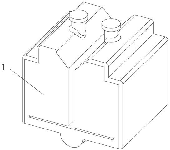
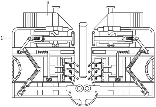
[0032] see figure 2 , image 3 and Figure 5 , a bulkhead support structure of a ship, comprising a shell 1, a trigger mechanism 2 is movably connected inside the shell 1, a correction mechanism 3 is fixedly connected to the side of the trigger mechanism 2 close to the inner wall of the shell 1, and a transmission mechanism is movably connected to the bottom of the trigger mechanism 2 4. The top of the transfer mechanism 4 is movably connected with a support mechanism 5 , and the top of the support mechanism 5 is fixedly connected with a guide block 6 at the upper end of the casing 1 .
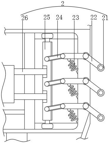
[0033] Further, the trigger mechanism 2 includes a roller 21 inside, the side of the roller 21 close to the correction mechanism 3 is movably connected with a lever 22, the bottom of the lever 22 is fixedly connected with a first tension spring 23, and the side of the lever 22 away from the roller 21 is movably connected There is a connecting rod 24, the side of the connecting rod 24 away f...
Embodiment 2
[0037] see figure 2 , Figure 6 and Figure 7 , a bulkhead support structure of a ship, comprising a shell 1, a trigger mechanism 2 is movably connected inside the shell 1, a correction mechanism 3 is fixedly connected to the side of the trigger mechanism 2 close to the inner wall of the shell 1, and a transmission mechanism is movably connected to the bottom of the trigger mechanism 2 4. The top of the transfer mechanism 4 is movably connected with a support mechanism 5 , and the top of the support mechanism 5 is fixedly connected with a guide block 6 at the upper end of the housing 1 .
[0038] Further, the transmission mechanism 4 includes a force rod 41 inside, the side of the force rod 41 close to the inner wall of the housing 1 is movably connected with a movable block 42, the outer surface of the movable block 42 is movably connected with a push block 43, and the top of the push block 43 is fixedly connected There is a curved bar 44, the top of the curved bar 44 is m...
Embodiment 3
[0042] see Figure 1-6 , a bulkhead support structure of a ship, comprising a shell 1, a trigger mechanism 2 is movably connected inside the shell 1, and a roller 21 is included inside the trigger mechanism 2, and a lever 22 is movably connected to the side of the roller 21 close to the correction mechanism 3, and the lever 22 The middle part is movably connected with a rotating shaft. The right end of the lever 22 is shorter than the left end. There are three levers 22, which are evenly distributed up and down. 24, the side of the connecting rod 24 away from the lever 22 is movably connected with a moving block 25, and the side of the moving block 25 away from the connecting rod 24 is fixedly connected with a fixed rod 26, and the end of the fixed rod 26 away from the moving block 25 is fixed close to the transmission block 31 One end of the rod 26 is fixedly connected, the force rod 41 is located at the bottom of the lever 22 , and the top of the movable rod 46 is movably co...
PUM
 Abstract
Description
Claims
Application Information
 - R&D Engineer
- R&D Manager
- IP Professional
- Industry Leading Data Capabilities
- Powerful AI technology
- Patent DNA Extraction
Browse by: Latest US Patents, China's latest patents, Technical Efficacy Thesaurus, Application Domain, Technology Topic, Popular Technical Reports.
© 2024 PatSnap. All rights reserved.Legal|Privacy policy|Modern Slavery Act Transparency Statement|Sitemap|About US| Contact US: help@patsnap.com