Copper parts feeding device

A technology for copper parts and clips is applied in the field of copper parts feeding devices, which can solve the problems of low operation safety, position deviation, and inability to guarantee safety.

Active Publication Date: 2022-07-15
伯朗特机器人股份有限公司
View PDF13 Cites 0 Cited by
  • Summary
  • Abstract
  • Description
  • Claims
  • Application Information

AI Technical Summary

Problems solved by technology

[0004] First, the safety cannot be guaranteed, manual and semi-automatic equipment work together, the loading and pressing actions are all done manually, and the operation safety is low;
[0005] The second is manual feeding of copper parts, and the positioning is deviated, resulting in improper assembly and pressing or position deviation resulting in defective products

Method used


Image

  • Copper parts feeding device
  • Copper parts feeding device
  • Copper parts feeding device

Examples


Embodiment Construction

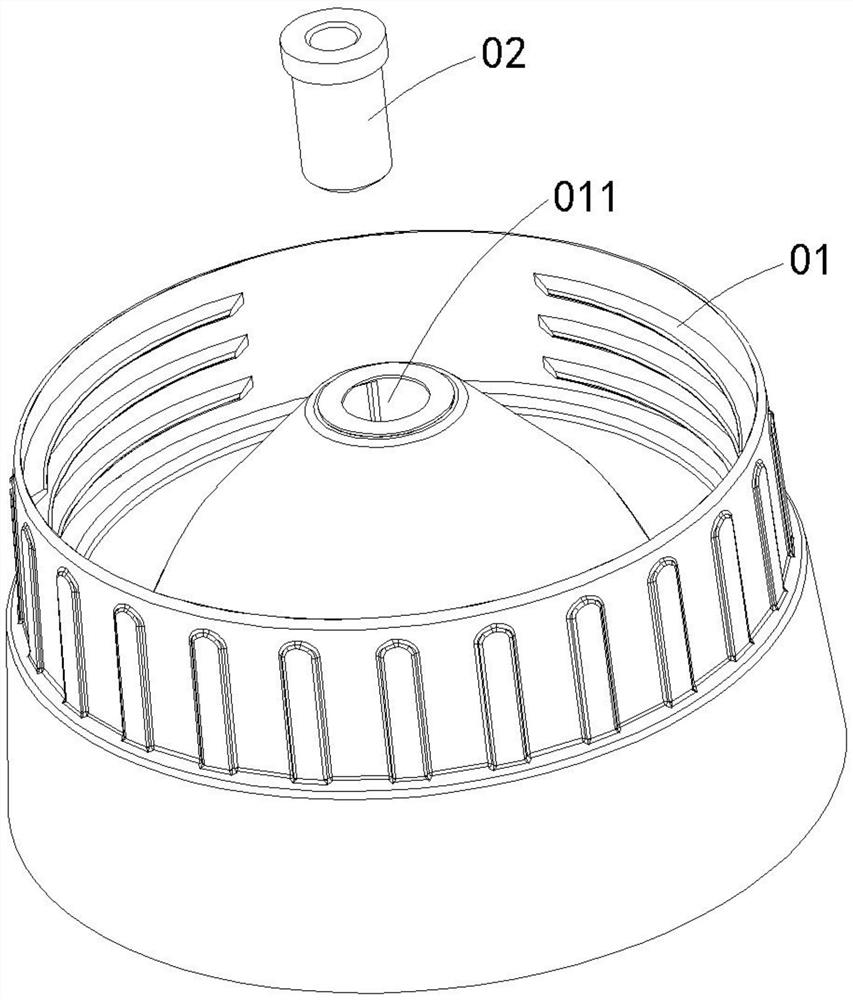
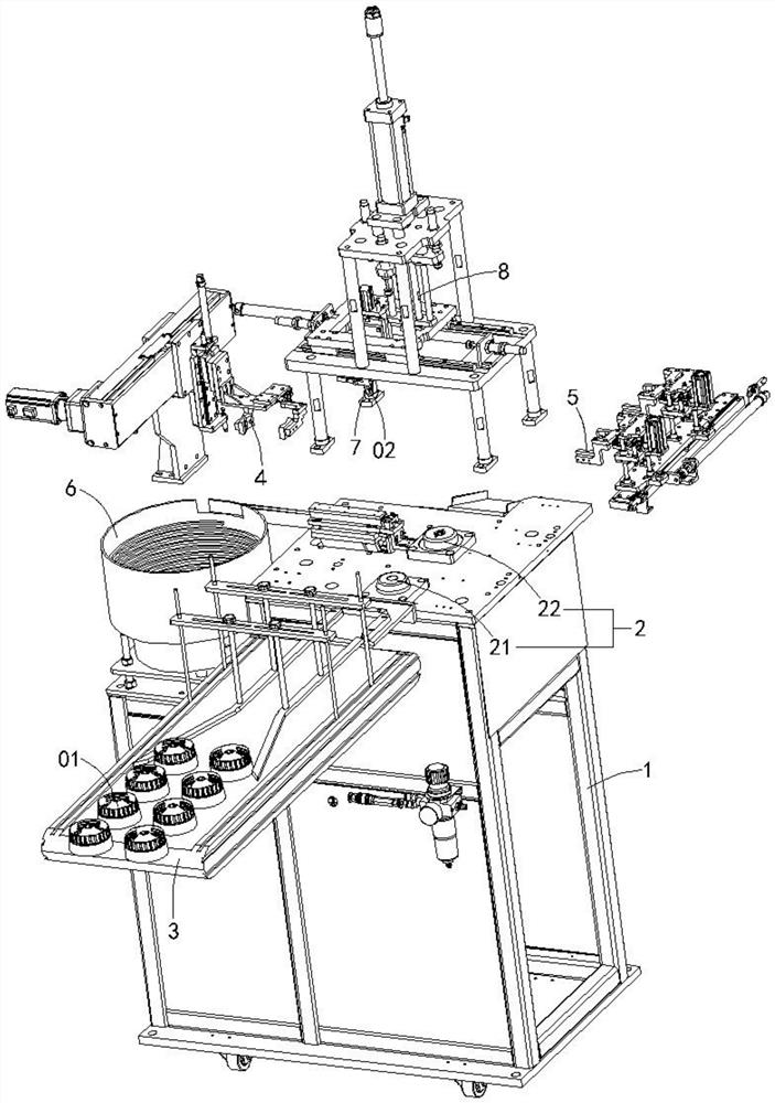
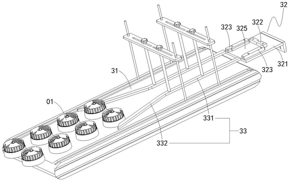
[0030] A copper part feeding device, see figure 2, which includes a frame 1 , a positioning mechanism 2 , a first feeding mechanism 3 , a first conveying mechanism 4 , a second conveying mechanism 5 , a second feeding mechanism 6 , a third conveying mechanism 7 , and a copper pressing mechanism 8 . The positioning mechanism 2 is used to position the base 01 so that the copper piece 02 can be pressed into the base 01 , and the positioning mechanism 2 includes a first positioning block 21 , a second positioning block 22 , a first positioning block 21 and a second positioning block 22 Both are arranged on the rack 1, the first positioning block 21 is used for positioning the base 01, and the second positioning block 22 is also used for positioning the base 01; There is a first positioning pin 23 protruding from the mounting hole 011 of the base 01 , the axis of the first positioning pin 23 and the axis of the mounting hole 011 of the base 01 are located on the same line. The fi...


PUM


Abstract

The invention relates to a copper piece feeding device. The copper parts feeding device of the present invention includes: a positioning mechanism, which includes a second positioning block and a first positioning pin, the second positioning block is used for positioning the base, and the first positioning pin is movably arranged at the the second positioning block; the third conveying mechanism, which is used to set the copper piece on the first positioning pin; the copper piece pressing mechanism, which includes a twelfth power source and a pressing rod, the first The output ends of the twelve power sources are connected with the push-in rod, and the copper piece is located within the movable range of the push-in rod. The copper parts feeding device of the present invention can liberate manual operations, realize the automatic loading of copper parts into products, ensure work efficiency and ensure assembly quality.

Description

technical field [0001] The invention relates to the field of machinery, in particular to a copper piece feeding device. Background technique [0002] see figure 1 , figure 1 It is a schematic diagram of the structure of a product used in a mixer. The product includes a base 01 and a copper piece 02. The base 01 is a hollow shell, and a mounting hole 011 is provided on the top of the base 01. The copper piece 02 is fixedly installed on the in the mounting hole 011. [0003] In the prior art, the materials are generally manually loaded onto the positioning table, and assembled by manual pressing equipment. And this prior art has the following shortcomings: [0004] First, the safety cannot be guaranteed. Manual and semi-automatic equipment work together. The feeding and pressing actions are all done manually, and the operation safety is low; [0005] Second, the manual feeding of copper parts has deviations in positioning, resulting in insufficient assembly and pressing o...

Claims


Application Information

Patent Timeline
Patent Type & Authority Patents(China)
IPC IPC(8): B23P19/02B23P19/027B23P19/00
CPCB23P19/02B23P19/027B23P19/00B23P19/001
Inventor 龚晓东
Owner 伯朗特机器人股份有限公司
Why Eureka
Try Eureka