Circuit board protective film cutting mechanism and method and film pasting device

A technology of protective film and circuit board, applied in transportation and packaging, coating of non-metallic protective layer, secondary treatment of printed circuit, etc., can solve the problems of reducing film cutting efficiency and increasing the number of film cutting equipment, so as to improve film supply Efficiency, the effect of reducing labor intensity

Inactive Publication Date: 2021-11-19
郑晓静
View PDF1 Cites 0 Cited by
  • Summary
  • Abstract
  • Description
  • Claims
  • Application Information

AI Technical Summary

Problems solved by technology

[0004] The existing technology has the following disadvantages: two down-cutting dies are used to cut the shape of the center hole of the circuit board and the shape of the outer contour of the circuit board in two separate steps, which increases the number of film cutting equipment and reduces the efficiency of film cutting

Method used


Image

  • Circuit board protective film cutting mechanism and method and film pasting device
  • Circuit board protective film cutting mechanism and method and film pasting device
  • Circuit board protective film cutting mechanism and method and film pasting device

Examples


Embodiment 1

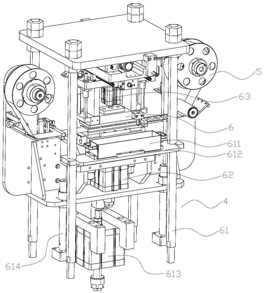
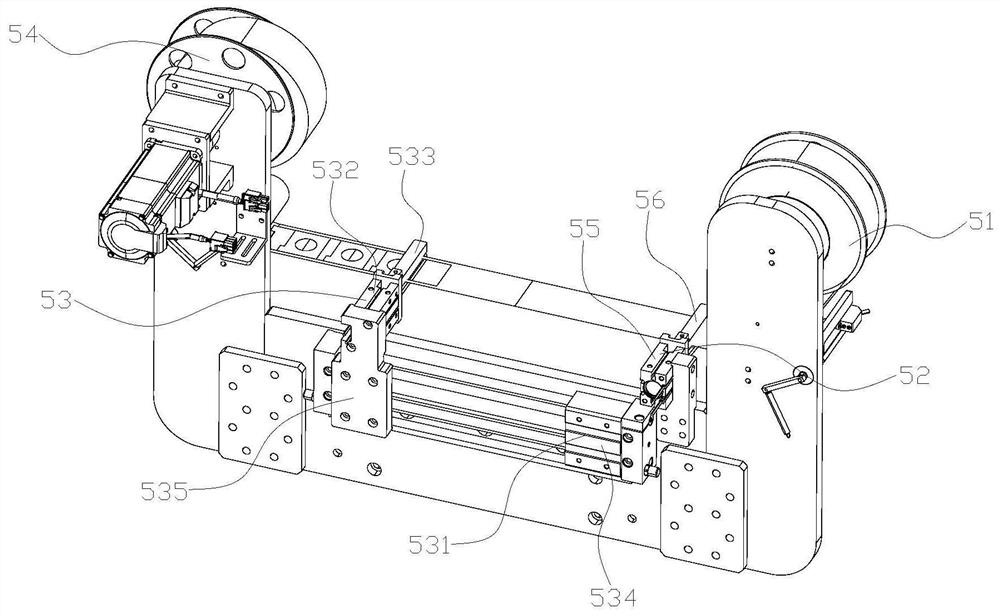
[0031] like figure 1 , image 3 As shown, the second film sticking device 4 includes a film feeding mechanism 5 and a film cutting mechanism 6; the film feeding mechanism 5 includes a feeding tray 51, a fixed clamping head 52, a movable clamping head 53 and a receiving tray 54; the fixed clamping head 52 includes a fixed cylinder 55 and a fixed head 56, the fixed cylinder 55 is fixed on the workbench, and its output end is connected with the upper and lower fixed heads 56, and the inner surface of the upper and lower fixed heads 56 is in contact with the upper and lower surfaces of the protective film; the movable clamping head 53 Including clamping head driving element 531, movable cylinder 532 and movable head 533; the driving end of clamping head driving element 531 is connected with movable cylinder 532, and the output ends of movable cylinder 532 are respectively connected with upper and lower movable heads 533, and the upper and lower The inner surface of the movable he...


PUM


Abstract

The invention relates to the field of circuit board protective film pasting, in particular to a circuit board protective film cutting mechanism, a method and a film pasting device. The mechanism comprises a film cutting machine frame, a lower cutting head and an upper cutting head, the lower cutting head and the upper cutting head are oppositely distributed up and down, the lower cutting head comprises a lower cutting air cylinder and a lower cutting mold, a main body cutting-off head and a central hole cutting-off head are arranged at the upper end of the lower cutting mold and protrude out of the upper surface of the lower cutting mold, the shapes and relative positions of main body cutting-off head and central hole cutting-off head correspond to the outer contour shape of a top surface film of a circuit board, the shape of a central hole of the top surface film of the circuit board and relative positions between the two, respectively, the upper cutting head comprises an upper cutting air cylinder and an upper cutting mold, an upper suction hole is formed in the bottom surface of the upper cutting mold, and the bottom face of the upper cutting mold makes contact with the upper surface of a protective film. According to the mechanism, the main body cutting-off head and the central hole cutting-off head are arranged on the lower cutting mold to cut off the central hole shape and the outer contour shape of the circuit board at the same time, the number of film cutting equipment is reduced, and the film cutting efficiency is improved.

Description

technical field [0001] The invention relates to the field of protective film sticking on circuit boards, in particular to a film cutting mechanism and method for protective film on circuit boards and a film sticking device. Background technique [0002] The circuit board, also known as the circuit board, is provided with conductive patterns and holes on the substrate to replace the chassis of the previous electronic components and realize the interconnection between electronic components, which can greatly reduce wiring and assembly errors and improve the automation level. and production efficiency. In the production process of printed circuit boards, the circuit boards need to be protected. The commonly used method is to mount protective films on the top and bottom of the circuit boards. [0003] Chinese invention patent application (publication number CN112601378A, publication date: 20210402) discloses an automatic film laminating machine based on PCB soft board, includin...

Claims


Application Information

Patent Timeline
Patent Type & Authority Applications(China)
IPC IPC(8): B26F1/44B26F1/14B26D7/02B26D5/00B65H20/16B29C63/02B29C63/00H05K3/28
CPCB26F1/44B26F1/14B26D7/025B26D5/005B65H20/16B29C63/02B29C63/0004H05K3/28
Inventor 郑晓静
Owner 郑晓静
Why Eureka
Try Eureka