A synchronous oil immersion device for inner and outer rings of bearings for mechanical processing
A technology of mechanical processing and inner and outer rings, which is applied to the device and coating of the surface coating liquid, which can solve the problems of unsatisfactory oil throwing effect, bearing collision, cumbersome operation, etc., achieve the best oil throwing effect and reduce labor intensity , The effect of simplifying the operation process
- Summary
- Abstract
- Description
- Claims
- Application Information
AI Technical Summary
Problems solved by technology
Method used
Image
Examples
Embodiment 1
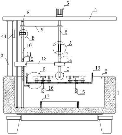
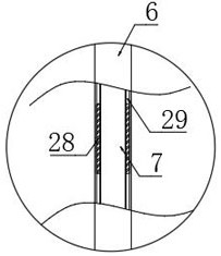
[0030] refer to Figure 1-6 , a synchronous oil immersion device for inner and outer rings of bearings for mechanical processing, comprising a housing 1, an oil immersion tank 2 is arranged on the upper end of the housing 1, a vertical plate 3 is fixedly connected to the upper end of the housing 1, and a horizontal plate 3 is installed on the upper end of the vertical plate 3 Plate 4, motor 5 is installed on the upper end of horizontal plate 4, the end of the output shaft of motor 5 runs through horizontal plate 4, and is fixedly connected with rotating tube 6, and the bottom of rotating tube 6 is provided with first rotating rod 7, and first rotating rod 7 The upper end of the upper end extends to the inside of the rotating tube 6, the second rotating rod 30 is arranged below the first rotating rod 7, and the rectangular sliding chamber 32 is arranged in the first rotating rod 7, and the upper end of the second rotating rod 30 extends to the rectangular sliding chamber 32, an...
Embodiment approach
[0031] As a kind of embodiment of the present invention, the lower end of horizontal plate 4 is provided with the moving mechanism that is used for moving screen frame 19, and moving mechanism comprises the second turning bar 10 that vertical rotation is connected in the bottom of oil immersion tank 2, and the second turning bar 10 A threaded layer 11 is provided on the top, and the threaded layer 11 is a threaded layer similar to a reciprocating screw rod to ensure that the unidirectional rotation of the second rotating rod 10 can drive the sliding block 12 to move up and down, and the threaded layer 11 of the second rotating rod 10 is partially threaded. Sliding block 12, horizontal plate 4 and the inner bottom of oil immersion tank 2 are vertically provided with guide rod, and guide rod runs through sliding block 12, and the right side of sliding block 12 is fixedly connected with connecting rod 13, and the right end of connecting rod 13 is fixedly connected with The connect...
Embodiment 2
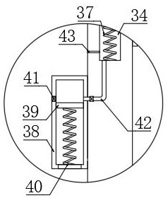
[0045] refer to Figure 7-9 The difference between this embodiment and Embodiment 1 is that two conductive blocks 33 are arranged on the left side inner wall of the oil immersion tank 2, the sliding block 12 is made of conductive material, and a vertical cavity 34 is arranged in the vertical plate 3, and the vertical The inner walls of both sides of the cavity 34 are provided with contact strips 36, and the vertical cavity 34 is provided with a conductive slider 35 for sliding up and down. The two contact strips 36 and the conductive slider 35 here together constitute a conductive assembly. , the conductive assembly is connected in series to the circuit where the electromagnet 44 is located, and the lower end of the conductive slider 35 is elastically connected to the inner bottom of the vertical cavity 34 through a restoring spring 37;
[0046] As an embodiment of the present invention, a trigger box 38 is provided on the left side wall of the riser 3, and a piston plate 39 f...
PUM
 Abstract
Description
Claims
Application Information
 - R&D
- Intellectual Property
- Life Sciences
- Materials
- Tech Scout
- Unparalleled Data Quality
- Higher Quality Content
- 60% Fewer Hallucinations
Browse by: Latest US Patents, China's latest patents, Technical Efficacy Thesaurus, Application Domain, Technology Topic, Popular Technical Reports.
© 2025 PatSnap. All rights reserved.Legal|Privacy policy|Modern Slavery Act Transparency Statement|Sitemap|About US| Contact US: help@patsnap.com


