Solenoid straight-through type relay

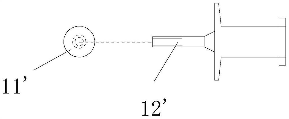
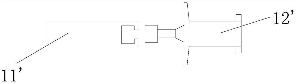
A straight-through, relay technology, applied in the direction of relays, electromagnetic relays, detailed information of electromagnetic relays, etc., can solve the problems of complex processing of iron core parts 1, large matching reluctance, and easy shaking, etc., to achieve simple and fast assembly process, avoid The effect of turning and strengthening the stability of the connection

Pending Publication Date: 2021-11-12
XIAMEN HONGFA ELECTRIC POWER CONTROLS
View PDF0 Cites 2 Cited by
  • Summary
  • Abstract
  • Description
  • Claims
  • Application Information

AI Technical Summary

Problems solved by technology

[0002] The iron core part 1' in the current magnetic latching relay is formed by connecting the iron core 11' and the push card 12'. There are two connection schemes, one is referred to Figure 1-2 As shown, the iron core 11' of the common iron core part 1' is a cylindrical iron core 11', and one end of the cylindrical iron core 11' is connected with the threaded push card 12' by forming a turning hole and threading. The iron core part 1' is complex to process, has many procedures, and the cost is too high, and the position of the friction area where the cylindrical iron core 11' moves relative to the wire frame is also uncontrollable, and deviations are prone to occur; when it is made into a magnetic holding structure, the permanent The magnetic circuit between the magnet and the cylindrical iron core 11' is a combination of a permanent magnet magnetic level plane and a circular arc of the cylindrical iron core 11', and the matching reluctance is relatively large; Figure 3-5 As shown, the iron core 11' of the iron core part 1' is a sheet iron core 11', by making one end of it into a non-closed annular through hole, and pushing the end of the card 12' to form a bump and an annular through hole. The holes are matched and connected to form the iron core part 1'. In this scheme, only one end of the sheet iron core 11' is connected to the push card 12', and the other end is not connected, which is prone to shaking and poor stability, and the sheet iron core 11' There will also be a certain space gap at the connection with the push card 12', which is prone to relative rotation and poor stability and reliability

Method used


Image

  • Solenoid straight-through type relay
  • Solenoid straight-through type relay
  • Solenoid straight-through type relay

Examples


Embodiment 1

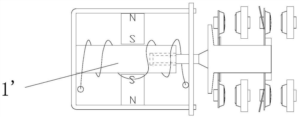
[0079] see Figure 6-17 As shown, a solenoid feed-through relay is provided, comprising: a base 2, a magnetic circuit part 3, a contact part 4 and a push card 12 arranged on the base 2, and the magnetic circuit part 3 controls the contact by pushing the card 12 The contacts of part 4 contact or separate;

[0080] The magnetic circuit component 3 includes a wire frame 31, a yoke and an iron core 11. The wire frame 31 is provided with a through hole in the contact separation direction for pushing one end of the card 12 into. The wire frame 31 is wound with a coil to form a magnetic control circuit. The iron core 11 is connected with the push card 12 to form the iron core part 1 and can move linearly in the wire frame 31, and the iron core part 1 cooperates with the through hole of the wire frame 31 to form a circumferential anti-rotation structure;

[0081] The iron core 11 is in the shape of a sheet, and at least one connection position is provided on one side of the thickness...

Embodiment 2

[0096] Embodiment 2, for the sake of brevity, this embodiment only describes the difference from Embodiment 1:

[0097] see Figure 18-19 As shown, the iron core 11 is a sheet-like U-shaped iron core 11 with two convex buds 7 on the inside and two sliding convex buds 10 on the outside, two grooves 8 on one side of the push card 12, There are two protruding buds 7 on the side, the protruding buds 7 on the inner side of the sheet-shaped U-shaped iron core 11 and the groove 8 on the side of the push card 12 form two connection positions to be connected, and then assemble to form the iron core part 1, and the inner part of the wire frame 31 There are sliding grooves 9 on both sides, the sliding convex buds 10 on the outside of the sheet-shaped U-shaped iron core 11 in the iron core part 1 and the convex buds 7 on the other side of the push card 12 cooperate with the sliding grooves 9 of the wire rack 31 to form a gap limit respectively. .

[0098] Of course, in other embodiments, ...

Embodiment 3

[0099] Embodiment 3, for the sake of brevity, this embodiment only describes the difference from Embodiment 2:

[0100] see Figure 20-22 As shown, the difference from Embodiment 2 is that the iron core 11 is a plane iron core 11, and the plane iron core 11 and the push card 12 have two sets of convex and groove structures (corresponding to form two connection positions) for connection.


PUM


Abstract

The invention relates to the technical field of relays, in particular to a solenoid straight-through type relay, which comprises a base, and a magnetic circuit component, a contact component and a pushing card which are arranged on the base, wherein the magnetic circuit component controls contact or separation of the contacts of the contact component through the pushing card, the magnetic circuit component comprises a coil holder and an iron core, the coil holder is provided with a through hole in the contact and separation direction of the contacts for one end of the pushing card to enter, a coil is wound outside the coil holder to form a magnetic control loop, the iron core and the pushing card are connected to form an iron core component, theiron core componentcan linearly move in the coil holder, the iron core component is matched with the coil holder through hole to form a circumferential anti-rotation structure, the iron core is sheet-shaped, and one side of the iron core in the thickness direction and one side of the pushing card are provided with at least one connecting position, so that the side surface of the iron core is matched with the side surface of the pushing card, and the iron core drives the pushing card to move back and forth. According to the invention, the iron core is low in machining difficulty, the assembling process of the iron core and the pushing card is simpler, more convenient and faster, and the stability of linear motion of the whole formed iron core component in the coil holder is guaranteed.

Description

technical field [0001] The invention relates to the technical field of relays, in particular to a solenoid straight-through relay. Background technique [0002] The iron core part 1' in the current magnetic latching relay is formed by connecting the iron core 11' and the push card 12'. There are two connection schemes. Figure 1-2 As shown, the iron core 11 ′ of the common iron core part 1 ′ is a cylindrical iron core 11 ′, and one end of the cylindrical iron core 11 ′ is connected with a threaded push card 12 ′ by forming a turning hole and threaded. The iron core part 1' is complicated to process, has many processes, and the cost is too high. Moreover, the position of the friction area of ​​the cylindrical iron core 11' and the relative movement of the wire rack is also uncontrollable, which is prone to deviation; The magnetic circuit between the magnet and the cylindrical iron core 11' is that the permanent magnet magnetic level plane cooperates with the circular arc of t...

Claims


Application Information

Patent Timeline
Patent Type & Authority Applications(China)
IPC IPC(8): H01H50/16H01H50/44H01H50/18
CPCH01H50/16H01H50/44H01H50/18
Inventor 钟叔明代文广何仲波黄庆阳吴意文
Owner XIAMEN HONGFA ELECTRIC POWER CONTROLS
Why Eureka
Try Eureka