Spline connecting structure for rear hub and rear flywheel of field bicycle

A technology of connecting structure and rear flywheel, applied in the direction of wheel hub, vehicle parts, transportation and packaging, etc., can solve the problem of slip wire and so on

Pending Publication Date: 2021-11-12
侯金胜
View PDF0 Cites 0 Cited by
  • Summary
  • Abstract
  • Description
  • Claims
  • Application Information

AI Technical Summary

Problems solved by technology

[0004] In order to overcome the deficiencies of the prior art above, the present invention provides a splined connection structure between the rear hub and the rear flywheel of a track bicycle, which can effectively solve the problem of slippage between the rear hub and the rear flywheel in the track bicycle during training. replacement problem

Method used


Image

  • Spline connecting structure for rear hub and rear flywheel of field bicycle
  • Spline connecting structure for rear hub and rear flywheel of field bicycle
  • Spline connecting structure for rear hub and rear flywheel of field bicycle

Examples


Embodiment 1

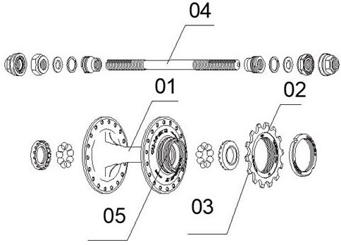
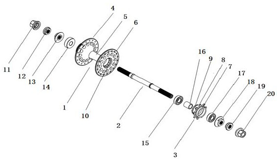
[0030] A spline connection structure between the rear hub and the rear flywheel of a track bicycle according to the present invention, please refer to Figure 1 to Figure 3 , the track bicycle includes a rear hub 1, a shaft 2 and a rear flywheel 3, the rear hub 1 and the rear flywheel 3 are sleeved on the shaft 2, and the two ends of the shaft 2 pass through a left nut 11 and a right nut 20 Fixed on the track bicycle frame, the rear hub 2 and the rear flywheel 3 are connected by splines. Existing track bikes such as figure 1 As shown, the rear hub 01 and the rear flywheel 02 are fixedly connected by threading. This connection method has the following problems. First, the rear hub 01 needs to be equipped with a rear adapter 05, and the adapter 05 is provided with threads. Then the adapter seat 05 is screwed into and fixedly connected with the rear flywheel 02, that is, the rear hub 01 is screwed into and fixedly connected with the rear flywheel 02. The setting of the adapter ...

Embodiment 2

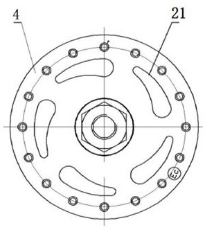
[0035] In this embodiment, the same technical features as in Embodiment 1 will not be repeated. The difference between this embodiment and Embodiment 1 is: a spline connection structure between the rear hub and the rear flywheel of a track bicycle of the present invention. Please refer to Figure 1 to Figure 2 , the rear hub 1 includes a front hub face 4, a hub shaft 5 and a rear hub face 6, the front hub face 4, hub shaft 5 and rear hub face 6 are integrally formed, and the front hub face 4 is fixed to one end of the hub shaft 5, The rear hub face 6 is fixed on the hub shaft 5, the part of the hub shaft 5 in front of the rear hub face 6 is the other end of the hub shaft 5, and an external spline 9 is arranged on the outer surface of the other end of the hub shaft 5, so that The other end of the hub shaft 5 is splined to the rear flywheel 3. The above structure specifically limits the spline structure of the rear hub 2 . Different from Embodiment 1, in this embodiment, an ext...


PUM

PropertyMeasurementUnit
Diameteraaaaaaaaaa

Abstract

The invention discloses a spline connecting structure for a rear hub and a rear flywheel of a field bicycle, the field bicycle comprises the rear hub, a shaft rod and the rear flywheel, the shaft rod is sleeved with the rear hub and the rear flywheel, two ends of the shaft rod are fixed on a frame of the field bicycle through a left nut and a right nut, and the rear hub is connected with the rear flywheel through a spline. Through the spline connecting structure of the rear hub and the rear flywheel, problems that the rear hub and the rear flywheel in a bicycle in field bicycle training are slipped and are frequently replaced are effectively solved. The spline connecting structure of the rear hub and the rear flywheel can reduce the diameter of the rear flywheel and reduce the number of teeth of the rear flywheel, so that the speed ratio of the field bicycle is increased, the riding speed of the field bicycle is increased, and the weight of the field bicycle is reduced.

Description

technical field [0001] The invention relates to the technical field of bicycle parts, in particular to a spline connection structure between a rear hub and a rear flywheel of a track bicycle. Background technique [0002] Track cycling is a mainstream event in the Olympic competition system. There are 10 gold medals produced in the venue, so it is deeply loved by people all over the world. In the track cycling competition, the total length of the bicycle is not more than 185 cm, the width is not more than 50 cm, and the weight is not less than 6.8 kg. The length of the seat should be between 24-30 cm, the distance between the central axis and the ground should be between 24-30 cm, and the diameter of the front and rear wheels of the bicycle must be the same. The diameter of the wheel is a maximum of 70 cm and a minimum of 55 cm. The bicycles used should be dead freewheels and should not be equipped with gear shifters and brakes. In track cycling, the gap between an Olympi...

Claims


Application Information

Patent Timeline
IPC IPC(8): B60B27/04B60B27/00
CPCB60B27/047B60B27/0047
Inventor 侯金胜
Owner 侯金胜
Why Eureka
Try Eureka