Unmanned aerial vehicle obstacle avoidance method and system and unmanned aerial vehicle cluster obstacle avoidance method and system
A UAV, obstacle avoidance technology, applied in control/adjustment systems, instruments, three-dimensional position/channel control, etc., can solve problems such as inapplicable prediction of unknown obstacles, dynamic obstacles, etc.
- Summary
- Abstract
- Description
- Claims
- Application Information
AI Technical Summary
Problems solved by technology
Method used
Image
Examples
Embodiment 1
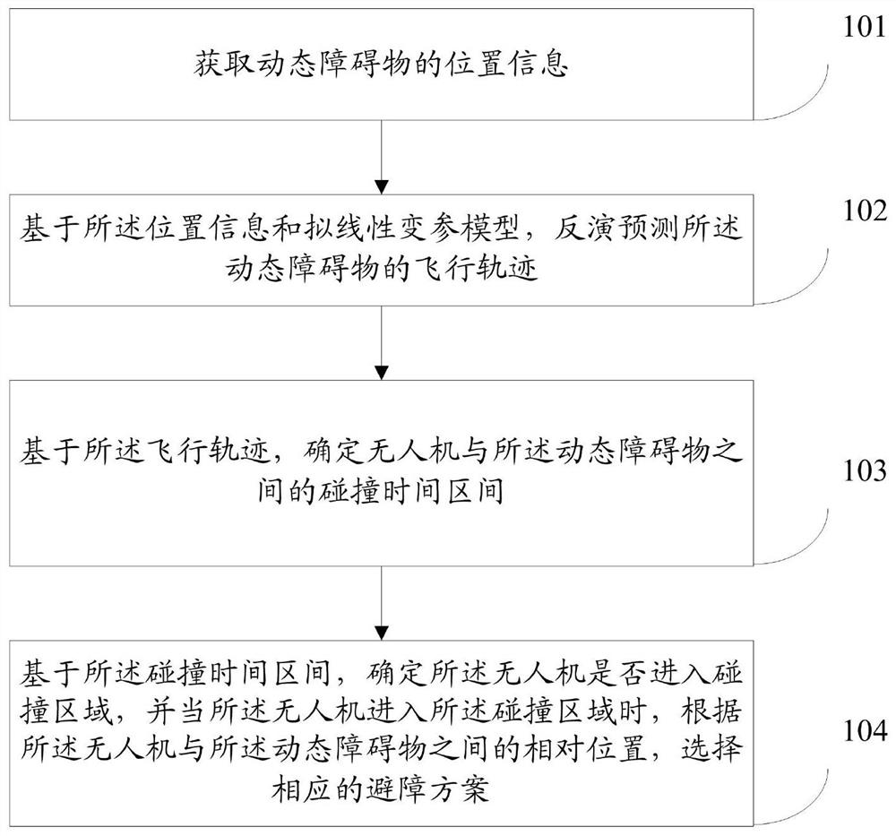
[0067] See figure 1 , a UAV obstacle avoidance method provided in this embodiment specifically includes the following steps.
[0068] Step 101: Obtain location information of dynamic obstacles.
[0069] In this embodiment, the position information of the dynamic obstacle is jointly acquired based on the laser radar and the binocular camera; the position information includes at least five position point information collected continuously.
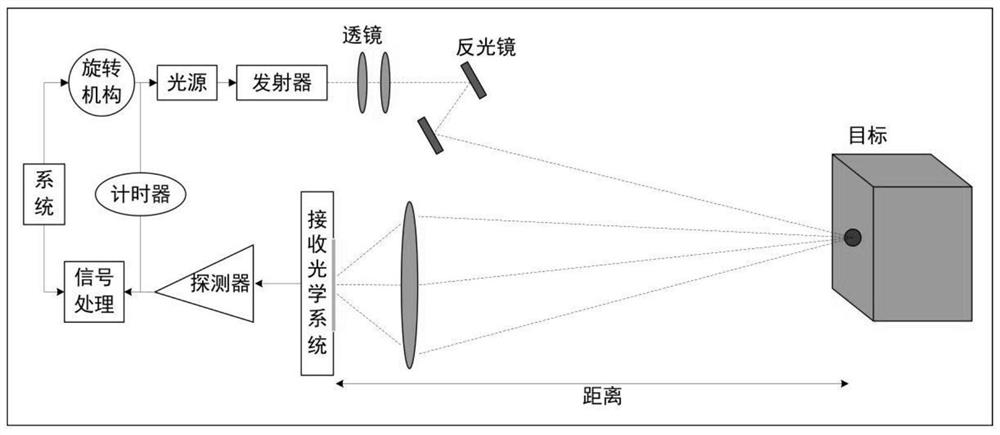
[0070] Since the laser radar has the advantages of short positioning, limited detection range, and fast speed, and the binocular camera has the characteristics of long-distance image positioning, the laser radar is used to work at a short distance, and the binocular camera is used to work at a long distance to achieve complementary advantages. The purpose of accurately obtaining the location information of dynamic obstacles.
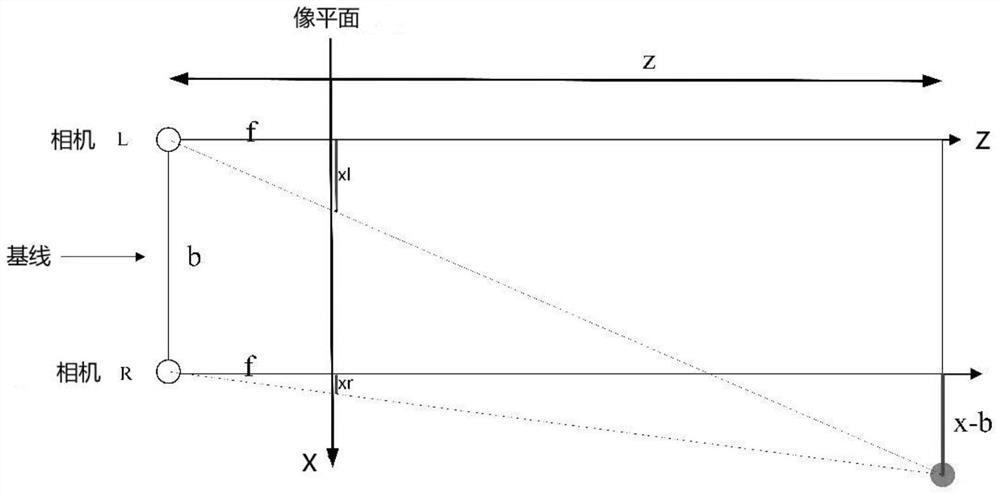
[0071] figure 2 The working principle of the binocular camera is shown, where f represents the focal length of t...
Embodiment 2
[0138] This embodiment provides a UAV obstacle avoidance system, such as Figure 7 shown, including:
[0139] The location information acquisition module 701 is configured to acquire location information of dynamic obstacles.
[0140] The inversion prediction module 702 is configured to invert and predict the flight trajectory of the dynamic obstacle based on the position information and the quasi-linear variable parameter model.
[0141] A collision time interval determining module 703, configured to determine a collision time interval between the UAV and the dynamic obstacle based on the flight trajectory.
[0142] The obstacle avoidance scheme selection module 704 is configured to determine whether the UAV enters the collision area based on the collision time interval, and when the UAV enters the collision area, according to the UAV and the The relative position between dynamic obstacles, select the corresponding obstacle avoidance scheme.
[0143] Among them, the system...
Embodiment 3
[0145] When UAV clusters perform tasks in a distributed manner, the UAVs are kept independent of each other. At the same time, in order to ensure the completion of the flight mission, the UAV formation flight is required to maintain consistency. The drone cluster selects the pilot drone, and the rest of the drones serve as follower drones. Once the pilot drone is unfortunately blown up, the optimization algorithm will launch a new pilot drone.
[0146] When the UAV cluster formation performs flight missions, following the UAV to follow the pilot UAV, due to communication delays or external interference, the cluster formation is often destroyed, and there is a large error between the actual flight trajectory and the specified path of the following UAV. , the advantage is that the control system of the UAV is known, and there is no need to reconstruct the system state. The pilot UAV only needs to send the target position information and control input. Even if there is information...
PUM
 Abstract
Description
Claims
Application Information
 - R&D
- Intellectual Property
- Life Sciences
- Materials
- Tech Scout
- Unparalleled Data Quality
- Higher Quality Content
- 60% Fewer Hallucinations
Browse by: Latest US Patents, China's latest patents, Technical Efficacy Thesaurus, Application Domain, Technology Topic, Popular Technical Reports.
© 2025 PatSnap. All rights reserved.Legal|Privacy policy|Modern Slavery Act Transparency Statement|Sitemap|About US| Contact US: help@patsnap.com


