Twisting mechanism for spinning machine

A technology of twisting mechanism and spinning machine, which is applied in the direction of textiles and papermaking, etc. It can solve the problems of reduced thread strength, insufficient thread strength, and insufficient thread tightness, so as to reduce fluctuations, achieve good results, and prevent tearing. Effect

Active Publication Date: 2021-11-05
JIANGSU NASKA NEW MATERIAL TECH CO LTD
View PDF14 Cites 1 Cited by
  • Summary
  • Abstract
  • Description
  • Claims
  • Application Information

AI Technical Summary

Problems solved by technology

[0004] The object of the present invention is to provide a kind of twisting mechanism for spinning machine, to solve the problem that in the twisting process, if each yarn is subjected to different tension, the time for each yarn to break is also different when the tension is received after the thread is formed. As a result, the strength of the formed wire is greatly reduced and the wire is not tight enough, and the surface is rough; if one of them breaks during twisting, and the equipment is not stopped in time, it will lead to the problem that the strength of the produced wire is not enough

Method used


Image

  • Twisting mechanism for spinning machine
  • Twisting mechanism for spinning machine
  • Twisting mechanism for spinning machine

Examples


Embodiment Construction

[0032] The technical solutions of the present invention will be clearly and completely described below in conjunction with the embodiments. Apparently, the described embodiments are only some of the embodiments of the present invention, not all of them. Based on the embodiments of the present invention, all other embodiments obtained by persons of ordinary skill in the art without creative efforts fall within the protection scope of the present invention.

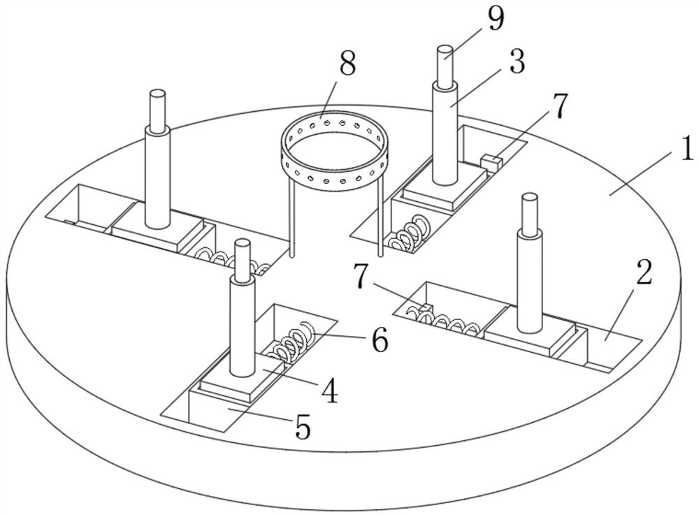
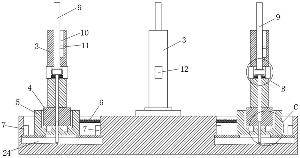
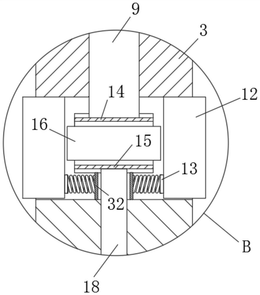
[0033] Such as Figure 1-Figure 9 As shown, a twisting mechanism for a spinning machine according to the present invention includes a turntable 1, and four chutes 2 are provided on the turntable 1, and a slider 5 is slidably connected to the chute 2, and the top of the slider 5 is A groove is provided, and a fixed block 4 is connected in the groove, and a vertical rod 3 is fixedly connected to the top of the fixed block 4, and a swivel 8 is connected above the center of the turntable 1 through a connecting rod, and the end ...


PUM


Abstract

The invention relates to the field of spinning machines, in particular to a twisting mechanism for a spinning machine. The twisting mechanism comprises a rotary table; a plurality of sliding grooves are formed in the rotary table; sliding blocks are slidably connected inside the sliding grooves; grooves are formed in the tops of the sliding blocks; fixed blocks are connected inside the grooves; vertical rods are fixedly connected to the tops of the fixed blocks; a rotating ring is connected to the upper portion of the center of the rotary table through a connecting rod; thrust springs are arranged at the ends, close to the rotating ring, of the sliding blocks; the two ends of each thrust spring are fixedly connected with the inner wall of the corresponding sliding groove and the corresponding sliding block; switches are mounted on the side walls, close to one side of the rotating ring, of the sliding grooves and the side walls, away from one side of the rotating ring, of the sliding grooves; a top sliding rod is vertically and slidably connected to the center of each vertical rod; an upper sliding plate is rotatably connected to the bottom of each top sliding rod; a lower sliding plate is arranged below each upper sliding plate; an air bag is arranged between each upper sliding plate and the corresponding lower sliding plate; side plates are arranged on the two sides of each air bag; the upper sliding plates and the lower sliding plates are slidably connected with the side plates; friction blocks are arranged at the two ends of each air bag; and the friction blocks penetrate through the side walls of the vertical rods and are in sliding connection with the side walls of the vertical rods.

Description

technical field [0001] The invention relates to the field of spinning machines, in particular to a twisting mechanism for spinning machines. Background technique [0002] Twisting is a process of winding the raw material into a thread. Multiple threads must be intertwined to make the thread stronger and more delicate. The tighter the thread is wound, the higher the twist, and the woven fabric will be relatively tight and fast. Good; twisting is an extremely important part of spinning. [0003] During the twisting process, if the tension of each yarn is different, the time for each yarn to break is also different when the tension is applied after the thread is formed, resulting in a greatly reduced strength of the thread and the thread is not tight enough and the surface is rough; when twisting If one of them breaks and the equipment is not stopped in time, the produced wire will not be strong enough. Contents of the invention [0004] The object of the present invention ...

Claims


Application Information

Patent Timeline
Patent Type & Authority Applications(China)
IPC IPC(8): D01H13/10D01H13/16
CPCD01H13/10D01H13/16
Inventor 沈月飞
Owner JIANGSU NASKA NEW MATERIAL TECH CO LTD
Why Eureka
Try Eureka