Display panel optical compensation method, device and machine readable storage medium

A display panel and optical compensation technology, applied in the direction of static indicators, instruments, etc., can solve the problems of uneven display, cyan color, and affecting the display effect of display equipment, so as to improve the display effect and avoid the effect of uneven display

Pending Publication Date: 2021-11-02
KUNSHAN GO VISIONOX OPTO ELECTRONICS CO LTD
View PDF0 Cites 0 Cited by
  • Summary
  • Abstract
  • Description
  • Claims
  • Application Information

AI Technical Summary

Problems solved by technology

However, because the orientation of the light-emitting units in the curved area and the non-curved area on the curved screen is different, and the reflection and refraction of the cover are also different, there will be a certain difference in the display brightness or display chromaticity between the curved area and the non-curved area. For example, there may be cyan or pink tinge at the edge of the surface, which will cause uneven display and affect the overall display effect of the display device

Method used


Image

  • Display panel optical compensation method, device and machine readable storage medium
  • Display panel optical compensation method, device and machine readable storage medium
  • Display panel optical compensation method, device and machine readable storage medium

Examples


Embodiment Construction

[0036] In order to make the purposes, technical solutions and advantages of the embodiments of the present application clearer, the technical solutions in the embodiments of the present application will be clearly and completely described below in conjunction with the drawings in the embodiments of the present application. Obviously, the described embodiments It is a part of the embodiments of this application, not all of them. The components of the embodiments of the application generally described and illustrated in the figures herein may be arranged and designed in a variety of different configurations.

[0037] Accordingly, the following detailed description of the embodiments of the application provided in the accompanying drawings is not intended to limit the scope of the claimed application, but merely represents selected embodiments of the application. Based on the embodiments in this application, all other embodiments obtained by persons of ordinary skill in the art w...


PUM


Abstract

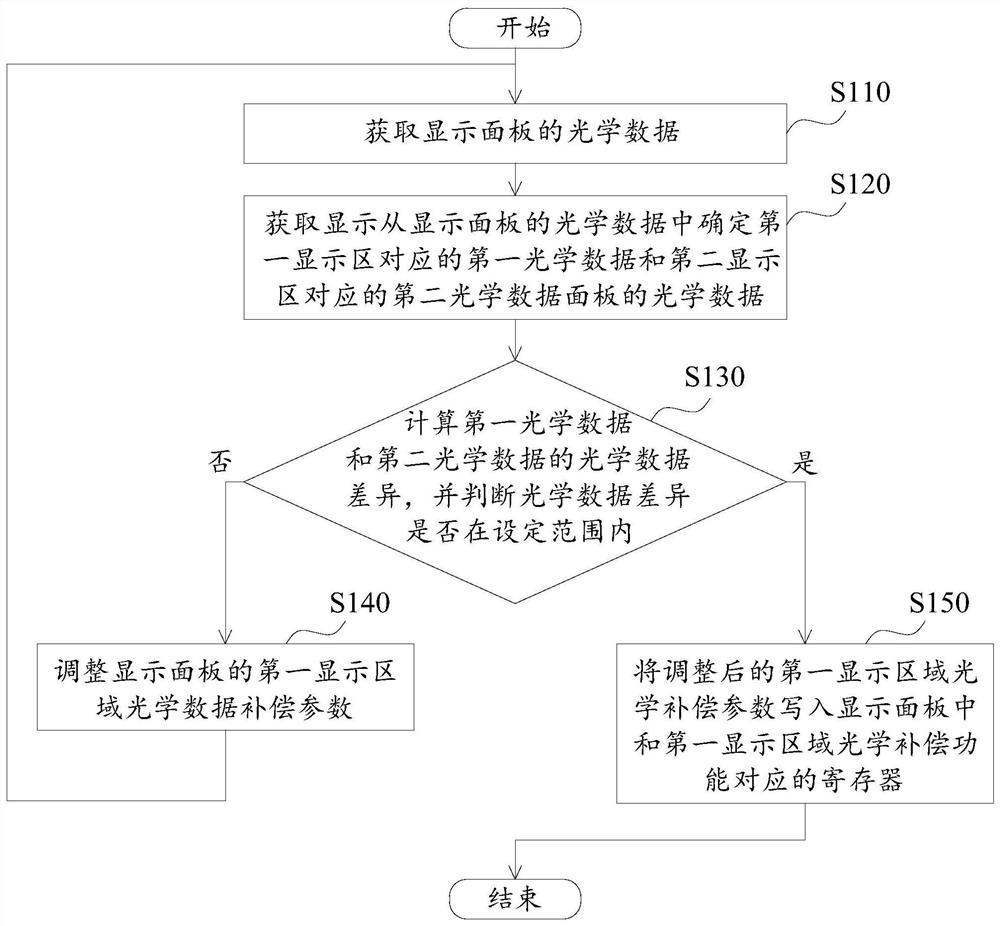
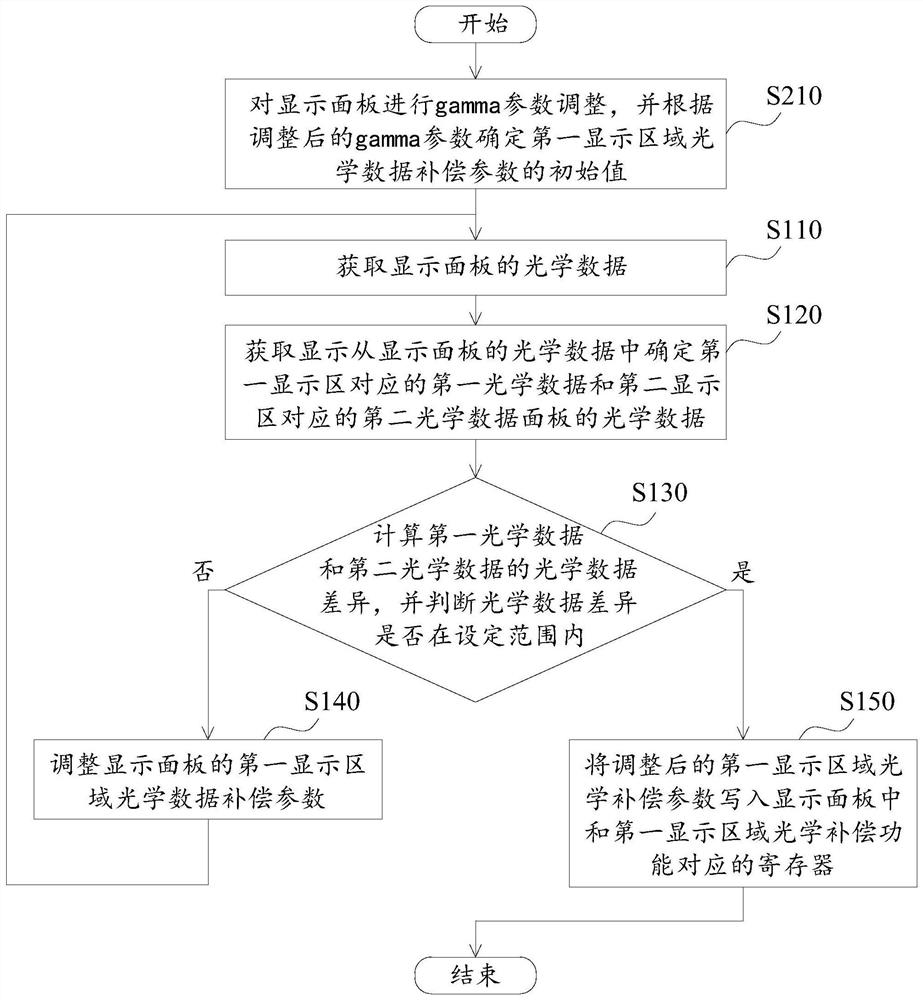
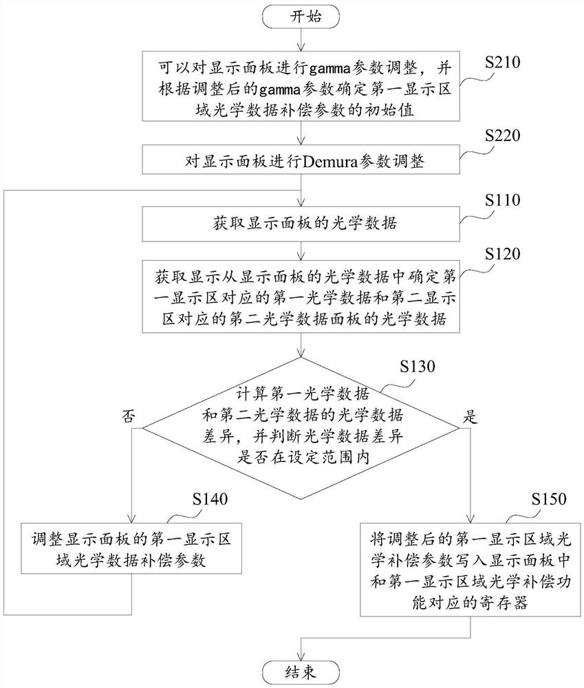
The embodiment of the invention provides a display panel optical compensation method, a device and a machine readable storage medium. The method comprises the following steps: obtaining the optical data of a display panel, calculating the optical data difference between the first optical data corresponding to a first display area and the second optical data corresponding to a second display area, judging whether the optical data difference is within a set range or not; and if not, adjusting the optical data compensation parameter of the first display area of the display panel. Thus, through a dynamic adjustment mode, the optical data of the display panel is collected, and the optical data compensation parameter of the first display area is adjusted according to the collected optical data. The display effect difference between the first display area and the second display area is gradually reduced until the optical data difference between the first display area and the second display area is within a set range. Therefore, the appropriate optical data compensation parameters of the first display area of the curved-surface display panel can be accurately determined, and the display effect of the curved-surface display panel is improved.

Description

technical field [0001] The present application relates to the field of display technology, in particular, to a display panel optical compensation method, device and machine-readable storage medium. Background technique [0002] In order to increase the screen-to-body ratio and improve visual experience, some display devices use a curved display panel whose edges are bent to form a curved screen. However, because the orientation of the light-emitting units in the curved area and the non-curved area on the curved screen is different, and the reflection and refraction of the cover are also different, there will be a certain difference in the display brightness or display chromaticity between the curved area and the non-curved area. For example, there may be cyan or pink tinge at the edge of the curved surface, which will lead to uneven display and affect the overall display effect of the display device. Contents of the invention [0003] In order to overcome the technical pr...

Claims


Application Information

Patent Timeline
IPC IPC(8): G09G3/20
CPCG09G3/20G09G3/2003G09G2320/0233G09G2320/0242G09G2380/02
Inventor 王铁钢姜海斌韩光光上官修宁马霄
Owner KUNSHAN GO VISIONOX OPTO ELECTRONICS CO LTD
Why Eureka
Try Eureka