Supercharge Your Innovation With Domain-Expert AI Agents!

Dovetail groove guide rail locking device and mounting and adjusting method

A dovetail groove and anti-loosening technology, applied in the field of guide rail transmission, can solve the problems of difficulty in adjusting the size of the friction force, potential safety hazards, affecting the transmission accuracy of the dovetail groove guide rail pair, etc.

Pending Publication Date: 2021-11-02
CSSC MARINE POWER
View PDF0 Cites 0 Cited by
  • Summary
  • Abstract
  • Description
  • Claims
  • Application Information

AI Technical Summary

Problems solved by technology

However, with the long-term operation of the dovetail guide pair, the wedge insert may move to one side and be damaged, seriously affecting the transmission accuracy of the dovetail guide pair
In addition, when the dovetail groove guide rail pair adopts the installation type with the dovetail groove facing up and the dovetail block facing down, generally a structure is used to increase the friction force between the two to prevent the free sliding of the dovetail block, but it is difficult to adjust the friction force accurately and conveniently. It affects work efficiency and has potential safety hazards

Method used


Image

  • Dovetail groove guide rail locking device and mounting and adjusting method
  • Dovetail groove guide rail locking device and mounting and adjusting method
  • Dovetail groove guide rail locking device and mounting and adjusting method

Examples


Embodiment Construction

[0023] The present invention will be further described below in conjunction with drawings and embodiments.

[0024] In the description of the present invention, terms such as "upper", "lower", "left", "right", "front", "rear", etc. indicating directions are based on the directions shown in the drawings, or are merely for the purpose of simplifying the description. , rather than indicating or implying that Ben must have a particular orientation.

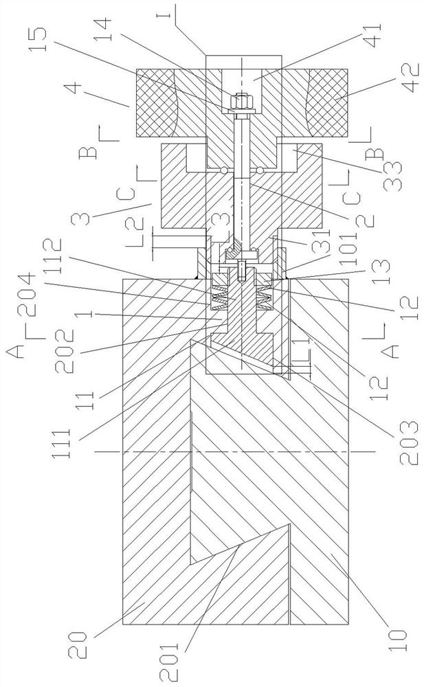
[0025] Such as figure 1 As shown, the installation type of the dovetail guide rail pair in this embodiment is the type under the dovetail block 20 on the dovetail body 10, and the present invention can also be used for the installation type under the dovetail body 10 on the dovetail block 20.

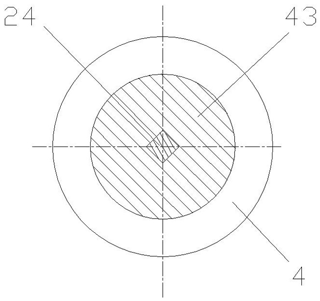
[0026] Such as Figure 1 to Figure 5 As shown, this embodiment includes a piston mechanism 1, a rotating shaft 2, a coarse adjustment nut 3 and a fine adjustment hand wheel 4 installed inside and outside one side of the dovetail tank body 20,...


PUM


Abstract

The invention discloses a dovetail groove guide rail locking device and a mounting and adjusting method. The dovetail groove guide rail locking device comprises a piston mechanism, a rotating shaft, a coarse adjustment nut and a fine adjustment hand wheel, wherein a piston is a combination of a wedge block and a cylinder, the upper side and the lower side of the wedge block are embedded into a through straight groove in the middle of one side of a dovetail groove, a piston rod transversely penetrates through a through hole in the side face of a through dovetail groove body, and a belleville spring set is embedded into a counter bore of the dovetail groove and the belleville spring set is positioned in the counter bore of the dovetail groove through the round nut. One end of the rotating shaft is in threaded connection with the end of the piston rod, and the other end of the rotating shaft sequentially penetrates through the coarse adjustment nut and the fine adjustment hand wheel and is fixed in a fine adjustment hand wheel counter bore in one end of the fine adjustment hand wheel through the fastening nut. The mounting and adjusting method comprises the steps: (1) mounting the piston mechanism, the coarse adjusting nut, the rotating shaft and the fine adjusting hand wheel, and (2) completing gap adjustment of the dovetail block and the dovetail groove. Coarse adjustment and fine adjustment are conducted through the coarse adjusting nut and the fine adjusting hand wheel which are arranged together in a sleeved mode, so that it is quite convenient to use, and the adjusting efficiency of the gap between the dovetail block and the dovetail groove is improved.

Description

technical field [0001] The invention relates to a dovetail groove guide rail device, in particular to a device and an installation adjustment method for preventing looseness between a dovetail block and a dovetail groove after long-term use due to increased gaps, and belongs to the technical field of guide rail transmission. Background technique [0002] The dovetail groove guide rail pair is composed of a dovetail block and a dovetail groove body. The dovetail block is embedded in the dovetail groove. There are two installation types: the dovetail block above the dovetail groove or the dovetail block below the dovetail groove. Because of its smooth movement and high precision, it is widely used in various instruments and equipment. The dovetail block and the dovetail tank are generally made of steel or cast iron. During long-term use, there will be different degrees of wear between the contact surfaces of the two, and the increase in the gap will affect the accuracy of the ...

Claims


Application Information

Patent Timeline
IPC IPC(8): F16C29/02F16D65/04F16D65/14F16D121/14
Inventor 赵俊方强龚洁朱文霞
Owner CSSC MARINE POWER
Features
  • R&D
  • Intellectual Property
  • Life Sciences
  • Materials
  • Tech Scout
  • Unparalleled Data Quality
  • Higher Quality Content
  • 60% Fewer Hallucinations
Learn More