Wireless charging device and system

A wireless charging and charging technology, applied in circuit devices, battery circuit devices, current collectors, etc., can solve the problems of inability to achieve long-distance energy transmission, high limitations, and point-to-point charging methods

Pending Publication Date: 2021-10-29
BOE TECH GRP CO LTD +1
View PDF15 Cites 0 Cited by
  • Summary
  • Abstract
  • Description
  • Claims
  • Application Information

AI Technical Summary

Problems solved by technology

[0002] The materials in the fully automated intelligent production line rely on the production line robots for handling, production and transfer. However, due to the limitation of battery power, the robot needs to return to the charging pile for power replenishment from time to time, which results in increased costs and reduced efficiency. question
[0003] The limitations of traditional wireless charging methods are very high. For example, although the radio wave charging method can transmit more than 10 meters from a relatively long distance, the power is small and the loss is large during the transmission process, which cannot meet the charging power requirements of the handling robot; Although the power of the magnetic induction wireless charging method is relatively high, the transmission distance is small, and it can only guarantee reliable charging within 10 cm
[0004] Therefore, the shortcomings of traditional wireless charging technology are very obvious: long-distance energy transmission cannot be achieved, the charging method can only be point-to-point (1VS.1), huge power loss during transmission, and low charging efficiency.

Method used


Image

  • Wireless charging device and system
  • Wireless charging device and system
  • Wireless charging device and system

Examples


Embodiment Construction

[0014] The application will be further described in detail below in conjunction with the accompanying drawings and embodiments. It should be understood that the specific embodiments described here are only used to explain related inventions, rather than to limit the invention. It should also be noted that, for ease of description, only parts related to the invention are shown in the drawings.

[0015] It should be noted that, in the case of no conflict, the embodiments in the present application and the features in the embodiments can be combined with each other. The present application will be described in detail below with reference to the accompanying drawings and embodiments.

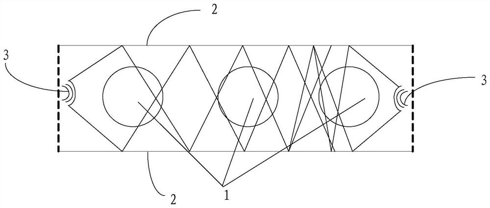
[0016] Please refer to figure 1 , this embodiment provides a wireless charging device, including at least one electromagnetic wave transmitter 3 configured to emit electromagnetic waves within the working area of ​​the wireless charging device;

[0017] It also includes a first electromagnetic in...


PUM


Abstract

The invention discloses a wireless charging device and system, and the device comprises at least one electromagnetic wave transmitter which is configured to transmit electromagnetic waves in a working region of the wireless charging device; the device also comprises a first electromagnetic induction module which is laid on the ground of the working area and is configured to convert electric energy into magnetic energy; the first electromagnetic induction module comprises a plurality of first electromagnetic induction coils, the front end of each first electromagnetic induction coil is provided with a receiver, the receivers are used for receiving electromagnetic waves emitted by the electromagnetic wave emitter, and the receivers are further connected to a power supply circuit, so that the power supply is used for converting electromagnetic waves received by the receivers into direct current and supplying power to the first electromagnetic induction coil. According to the technical scheme provided by the embodiment of the invention, the electromagnetic induction technology and the radio wave technology are combined for wireless charging, and the two charging modes make up each other, so the charging device can meet the requirements of long-distance and high-power charging, and can realize the charging function in a working area.

Description

technical field [0001] The invention relates to the field of wireless charging, in particular to a wireless charging device and system. Background technique [0002] The materials in the fully automated intelligent production line rely on the production line robots for handling, production and transfer. However, due to the limitation of battery power, the robot needs to return to the charging pile for power replenishment from time to time, which results in increased costs and reduced efficiency. question. [0003] The limitations of traditional wireless charging methods are very high. For example, although the radio wave charging method can transmit more than 10 meters from a relatively long distance, the power is small and the loss is large during the transmission process, which cannot meet the charging power requirements of the handling robot; Although the magnetic induction wireless charging method has relatively high power, the transmission distance is small, and it can...

Claims


Application Information

Patent Timeline
Patent Type & Authority Applications(China)
IPC IPC(8): H02J50/12H02J50/20H02J50/40H02J7/00
CPCH02J50/12H02J50/20H02J50/40
Inventor 胡大海刘国王永波胡忠孟晨刘彬彬
Owner BOE TECH GRP CO LTD
Why Eureka
Try Eureka