Antenna rotating and lodging mechanism for shelter

An antenna and shelter technology, applied in the field of antenna rotation and lodging mechanism for shelters, can solve the problems of inability to work, inconvenient installation and maintenance, complex structure design, etc., and achieve the effects of simple installation, cost saving and simple structure

Pending Publication Date: 2021-10-29
NINGBO SHUXIANG NEW MATERIAL
View PDF2 Cites 0 Cited by
  • Summary
  • Abstract
  • Description
  • Claims
  • Application Information

AI Technical Summary

Problems solved by technology

This utility model solution can only be that the antenna is laid down horizontally or erected at 90°, and cannot be accurately positioned between 0° and 90°, and it does not have the function of horizontal rotation
[0005] Another example is the utility model whose authorized publication number is CN211295351U, which belongs to the field of vehicle-mounted antenna horizontal rotation adjustment and lodging control technology, and relates to an electric lodging mechanism with antenna horizontal rotation function, which includes a base fixedly installed on the top of the vehicle from bottom to top, and a relative The lodging turret rotates on the base, the horizontal rotation adjustment device, the antenna support rod and the antenna installed on the antenna support rod. The horizontal rotation adjustment device includes the bottom plate of the rotary platform fixed on the top of the lodging The slewing bearing seat on the top, the slewing intermediate shaft installed in the slewing bearing seat, the motor reducer connected to the slewing intermediate shaft and the slewing motor driving the motor reducer to rotate solve the problem that the existing antenna lodging mechanism does not have antenna horizontal rotation adjustment function, it is not convenient to adjust the antenna orientation angle
Although this utility model has the function of horizontal rotation, there are problems such as electric rotation but no manual control, failure to work when power is off, complicated structural design, inconvenient installation and maintenance, and high cost.

Method used


Image

  • Antenna rotating and lodging mechanism for shelter
  • Antenna rotating and lodging mechanism for shelter
  • Antenna rotating and lodging mechanism for shelter

Examples


Embodiment approach

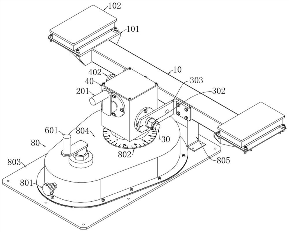
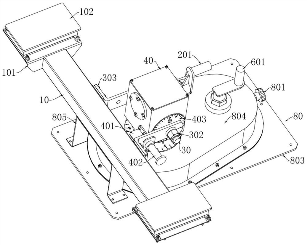
[0049] The end of the first output shaft 30 outside the first housing 40 is provided with a connection structure, and the antenna stand 10 is fixedly connected to the first output shaft 30 through the connection structure. In the specific implementation process, the antenna frame 10 is a rod-shaped structure, and the antenna frame 10 is connected to the first output shaft 30 through a connecting structure. There are two implementation modes, specifically:

[0050] The first embodiment is: the connection structure is a locking nut 302 , one end of the first output shaft 30 is located inside the first housing 40 , and the other end is located outside the first housing 40 . The length direction of the antenna frame 10 is perpendicular to the length direction of the first output shaft 30 , and one end of the antenna frame 10 is provided with a mounting structure 101 , and the other end is directly fixed to the outer end of the first output shaft 30 through a connecting structure. ...


PUM


Abstract

The invention discloses an antenna rotating and lodging mechanism for a shelter. The mechanism is characterized in that the mechanism comprises an antenna frame, a rotating assembly, and a lodging assembly; at least one mounting structure is arranged on the antenna frame and is used for mounting an antenna for the shelter; the antenna frame is arranged on the lodging assembly, and the antenna frame has a stroke of rotating around a horizontal shaft on the lodging assembly so as to drive the antenna on the antenna frame to lodge; the lodging assembly is arranged on the rotating assembly, and the lodging assembly has a stroke of rotating around a vertical shaft on the rotating assembly so as to be used for driving the lodging assembly to rotate on a horizontal plane and further driving the antenna on the antenna frame to rotate. The antenna rotating and lodging mechanism is small in design size, convenient to operate and complete in function, can enable the antenna to have lodging and rotating functions at the same time, and can be effectively applied to the technical field of communication auxiliary equipment.

Description

technical field [0001] The invention relates to the technical field of communication auxiliary equipment, in particular to an antenna rotation and lodging mechanism for shelters. Background technique [0002] As a carrying environment for equipment and personnel, the shelter has good maneuverability and environmental adaptability, and is widely used in various emergency support and field operations, especially as a carrying tool for mobile electronic information systems. The antenna on the shelter is a key component in the information transmission link, requiring it to be able to receive or transmit information flexibly. [0003] Most of the existing antenna lodging mechanisms only have the lodging function: [0004] For example, the utility model with the authorized publication number CN206774658U discloses a manual antenna lodging mechanism, which includes a fixed mount fixed on the roof, a rotating body arranged in the fixed mount, and a locking device for restricting th...

Claims


Application Information

Patent Timeline
Patent Type & Authority Applications(China)
IPC IPC(8): H01Q1/12H01Q3/08
CPCH01Q1/12H01Q3/08
Inventor 陈超陶名扬鲍方明王国华金佳杰苏清萍
Owner NINGBO SHUXIANG NEW MATERIAL
Why Eureka
Try Eureka