
Unmanned aerial vehicle take-off power assisting device arranged on wall

A technology for assisting devices and drones, applied in the field of drones, can solve the problems of little power assisting, shaking of drones, affecting the assisting effect of drones, etc., and achieve the effect of reducing work intensity and being convenient and quick to use.

Inactive Publication Date: 2021-10-29
湖州泰益智能科技有限公司
View PDF0 Cites 0 Cited by
  • Summary
  • Abstract
  • Description
  • Claims
  • Application Information

AI Technical Summary

Problems solved by technology

Due to the lack of power assistance during the take-off process of the UAV, the difficulty of taking off has increased
[0003] The existing UAV take-off assist device provides assistance for the UAV take-off through a constant fan, but due to the different sizes of the UAV wings, the required assistance is different, and when the assist provided by the device is too large, it may It causes the UAV to shake during the ascent process, which reduces the stability of the UAV, and the power assistance provided by the device is too small, which will cause the device to play a negligible role in the UAV's ascent process, thus affecting the device's response to different The boost effect of wing-sized drones

Method used


Image

  • Unmanned aerial vehicle take-off power assisting device arranged on wall
  • Unmanned aerial vehicle take-off power assisting device arranged on wall
  • Unmanned aerial vehicle take-off power assisting device arranged on wall

Examples


Embodiment Construction

[0025] The following will clearly and completely describe the technical solutions in the embodiments of the present invention with reference to the accompanying drawings in the embodiments of the present invention. Obviously, the described embodiments are only some, not all, embodiments of the present invention.

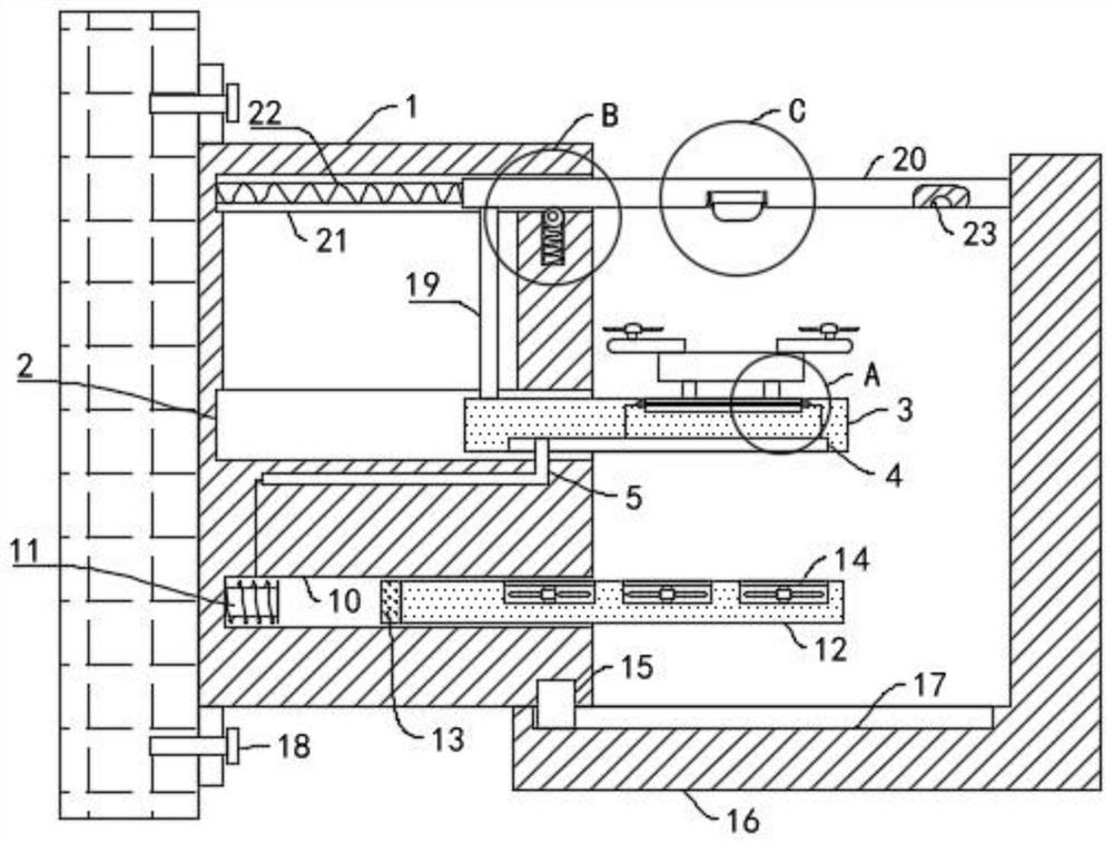
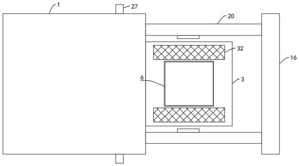
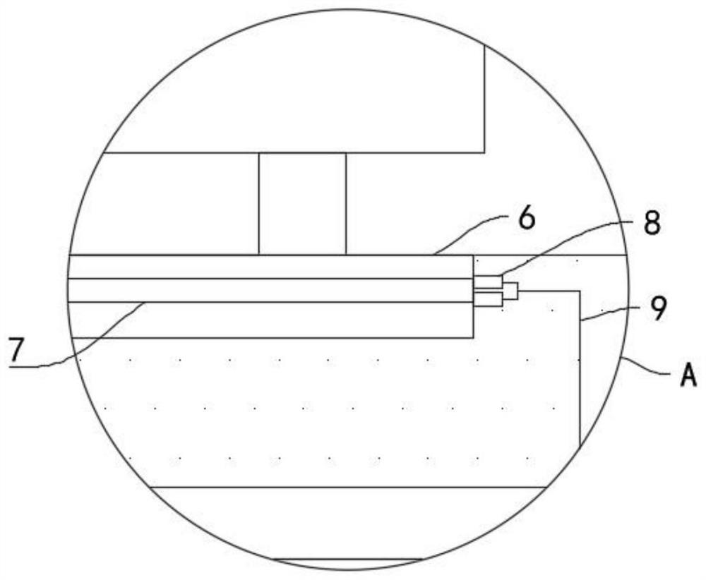
[0026] refer to Figure 1-5 , a UAV take-off assisting device placed on the wall, including a housing 1, a first inner cavity 2 is opened in the housing 1, a horizontal plate 3 is slidably connected to the first inner cavity 2, and a horizontal plate 3 is installed on the horizontal plate 3. Conductive slot 4, a conductive rod 5 is fixedly installed in the housing 1, a placement platform 6 is installed on the horizontal plate 3, one end of the conductive rod 5 is slidably connected with the conductive slot 4, and a second inner cavity 10 is provided in the housing 1. An electromagnetic block 11 is fixedly installed in the second inner cavity 10, and a mounting plate ...


PUM


Abstract

The invention discloses an unmanned aerial vehicle take-off power assisting device arranged on a wall, and relates to the technical field of unmanned aerial vehicles. The unmanned aerial vehicle take-off power assisting device comprises a shell, a first inner cavity is formed in the shell, a transverse plate is slidably connected in the first inner cavity, a conductive groove is formed in the transverse plate, a conductive rod is fixedly installed in the shell, a placement table is installed on the transverse plate, one end of the conductive rod is slidably connected with the conductive groove, a second inner cavity is formed in the shell, and an electromagnetic block is fixedly installed in the second inner cavity. By arranging an accent light, an illumination plate, a photo resistor, an electromagnetic block, a magnetic block and a fan, the magnitude of current introduced into the electromagnetic block is controlled by shielding the illumination range of the accent light on the illumination plate through the wings of the unmanned aerial vehicle, so that the magnetism of the electromagnetic block can be controlled, and then the output intensity of the fan is adjusted; and the situation that the stability of the unmanned aerial vehicle in the take-off process is affected by too large assisting force of the take-off assisting device is avoided, and meanwhile the situation that the assisting device loses the assisting effect due to too small assisting force is also avoided.

Description

technical field [0001] The invention relates to the technical field of unmanned aerial vehicles, in particular to a take-off assisting device for an unmanned aerial vehicle placed on a wall. Background technique [0002] At present, the rapid increase in urban population has led to extreme tension in urban space, and urban ground resources tend to be exhausted. It is of great significance to seek space from the sky and explore the use of urban air resources to build public infrastructure. The application of drones plays a vital role in the upgrading and transformation of urban public service infrastructure. Due to the lack of power assistance during the take-off process of the UAV, the take-off difficulty is increased. [0003] The existing UAV take-off assist device provides assistance for the UAV take-off through a constant fan, but due to the different sizes of the UAV wings, the required assistance is different, and when the device provides too much assistance, it may ...

Claims


Application Information

Patent Timeline
Patent Type & Authority Applications(China)
IPC IPC(8): B64F1/04
CPCB64F1/04
Inventor 沈明明
Owner 湖州泰益智能科技有限公司
Learn More