
Testing device for testing a distance sensor that operates using electromagnetic waves

A technology of distance sensor and test equipment, applied in the direction of re-radiation of electromagnetic waves, reflection/re-radiation of radio waves, utilization of re-radiation, etc., can solve problems such as expensive and time-consuming

Pending Publication Date: 2021-10-22
디스페이스게엠베하
View PDF6 Cites 0 Cited by
  • Summary
  • Abstract
  • Description
  • Claims
  • Application Information

AI Technical Summary

Problems solved by technology

This has traditionally been done through very expensive and time-consuming practical driving tests

Method used


Image

  • Testing device for testing a distance sensor that operates using electromagnetic waves
  • Testing device for testing a distance sensor that operates using electromagnetic waves
  • Testing device for testing a distance sensor that operates using electromagnetic waves

Examples


Embodiment Construction

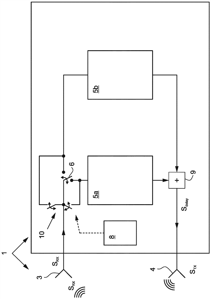
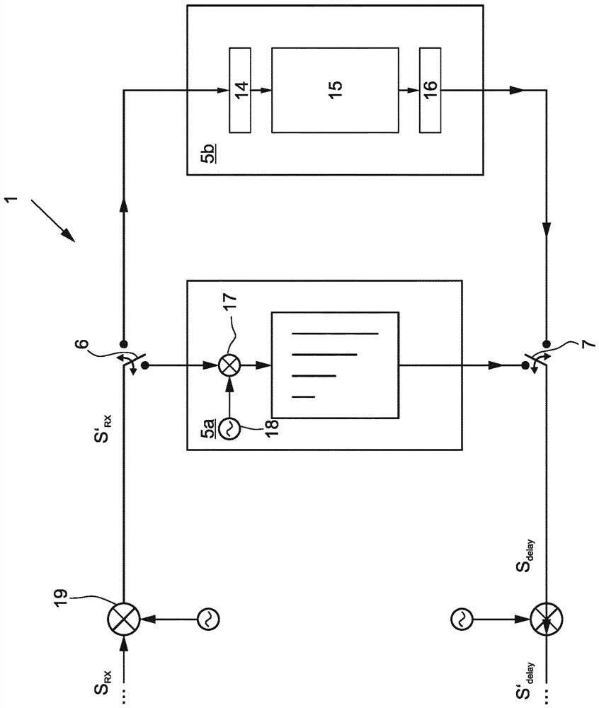
[0038] exist Figures 1 to 7 The test equipment 1 for testing the distance sensor 2 working with electromagnetic waves is shown respectively in figure 1 is schematically shown in . The distance sensor 2 emits electromagnetic free-space waves towards the direction of the test device 1 and receives the simulated electromagnetic reflection signal S generated by the test device 1 TX . For receiving the free-space waves emitted by the distance sensor 2, the test device 1 has a receiving element 3 and for emitting the simulated electromagnetic reflection signal S TX , the testing device 1 has a radiating element 4 . The distance sensor 2 itself does not belong together to the test device 1 . Receive signal S RX or receive signal from S RX The derived signal S' RX It is guided via a time delay circuit 5 , wherein the time delay circuit 5 can be predetermined with a time delay within a certain range. The input signal of the time delay circuit 5 is thus time-delayed into a time...


PUM


Abstract

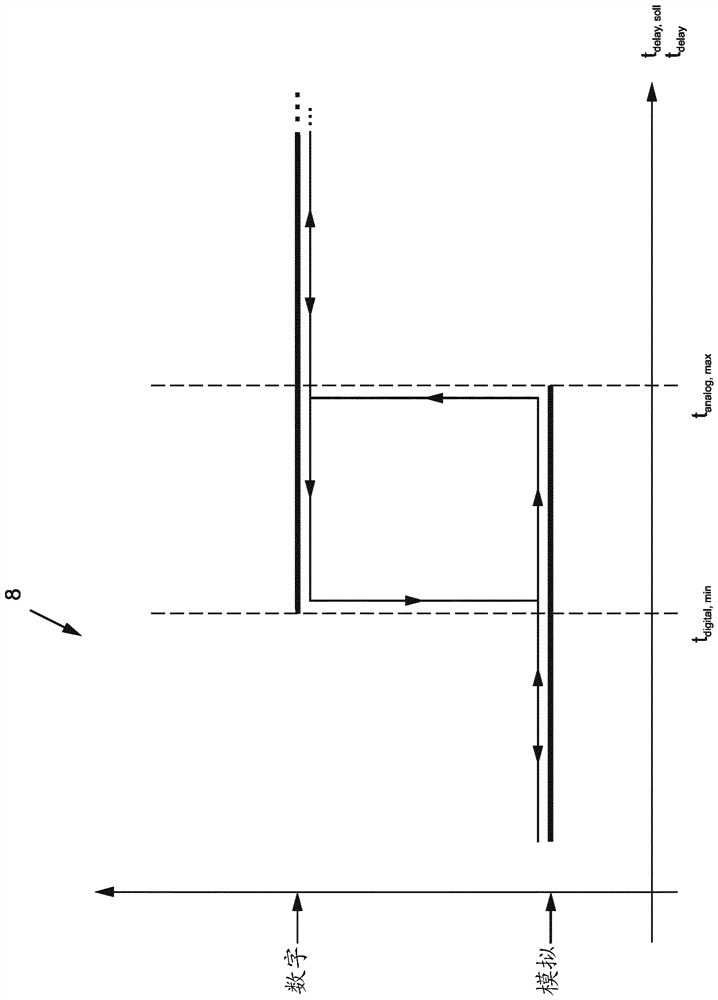
The invention relates to a testing device (1) for testing a distance sensor (2) that operates using electromagnetic waves, comprising a receiving element (3) for receiving an electromagnetic free-space wave as a received signal SRX and an emission element (4) for emitting a simulated electromagnetic reflection signal STX, the received signal SRX or a signal S'RX derived from the received signal SRX being fed through a time-delay circuit (5) having a specifiable time delay tdelay, soll and thus being time-delayed to form a time-delayed signal Sdelay, the time-delayed signal Sdelay or a signal S'delay derived from the time-delayed signal Sdelay being emitted as the simulated reflection signal STX by means of the emission element (4). A large range of specifiable time delays can be covered because the time-delay circuit (5) comprises an analog delay segment (5a) having a specifiable time delay tdelay, soll and a digital delay segment (5b) having a likewise specifiable time delay tdelay, soll , because the analog delay segment (5a) effects shorter time delays than the digital delay segment (5b), apart from a possible range of overlap, and because the received signal SRX or the signal S'RX derived from the received signal SRX is switched either to the input of the analog delay segment (5a) or to the input of the digital delay segment (5b) by means of an input switching apparatus (6) and the signal becomes the time-delayed signal Sdelay after passing through the switched delay segment.

Description

technical field [0001] The invention relates to a test device for testing distance sensors operating with electromagnetic waves, said test device having a device for receiving electromagnetic free-space waves as received signal S RX The receiving element has the electromagnetic reflection signal S for transmitting the emulation TX The transmitting element, where the received signal S RX or receive signal from the S RX The derived signal S' RX Conducted via a time-delay circuit with a predeterminable time delay and thus time-delayed to a time-delayed signal S delay , where the time-delayed signal S delay or from the time-delayed signal S delay The derived signal S' delay As the simulated reflection signal S TX is emitted via the emitting element. Background technique [0002] Test devices of the kind described above for testing distance sensors are known recently from the field of control device development and control device testing, especially in the automotive sect...

Claims


Application Information

Patent Timeline
Patent Type & Authority Applications(China)
IPC IPC(8): G01S7/40G01S7/497G01S13/931G01S17/931G01S13/34
CPCG01S7/4052G01S7/497G01S13/931G01S17/931G01S2013/9323G01S7/4065G01S7/4086G01S7/4095G01S7/40G01S13/08G01S7/4082
Inventor J·保罗J·沃特金斯M·罗茨曼
Owner 디스페이스게엠베하
Learn More