Rigid hinge device of folding product

A rigid hinge and product technology, applied in the direction of pivot connection, can solve the problems of large lateral swing, poor connection rigidity, and large sway, and achieve the effect of simple structure of rigid hinge, low material consumption and high reliability

Pending Publication Date: 2021-10-12
薛勇
View PDF0 Cites 0 Cited by
  • Summary
  • Abstract
  • Description
  • Claims
  • Application Information

AI Technical Summary

Problems solved by technology

[0002] In the existing folding products or folding components, including tourism and leisure folding products, when cross hinges are used for two-dimensional or three-dimensional folding and unfolding, a single cross hinge structure is adopted, which has a high hinge Rigidity, however, in order to make the product or component folded into a smaller volume, it is necessary to use a composite cross-tube hinge, that is, when more than two sets of tubes are cross-hinged, because the hinge is a point hinge or the bonding surface of the hinge point is very small, plus The gap between the hinge holes, the rigidity of the hinged connection is very poor, the system rigidity is low, and the degree of shaking is large, such as the common folding door of the company's gate; when multiple non-intersecting single pipes are used for hinged connection, if Without rigid hinge measures, the rigidity of the hinged connection of multiple single pipes will be worse, the lateral swing will be greater, and it is almost unusable
Therefore, people hope to solve the problem of relatively poor hinge rigidity of the composite cross-hinged structure and multiple sets of non-cross-hinged structures in folding products or folding components. A rigid hinge method or a rigid hinge device with relatively high system hinge rigidity

Method used


Image

  • Rigid hinge device of folding product
  • Rigid hinge device of folding product
  • Rigid hinge device of folding product

Examples


Embodiment Construction

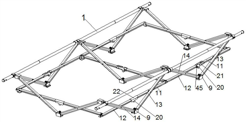
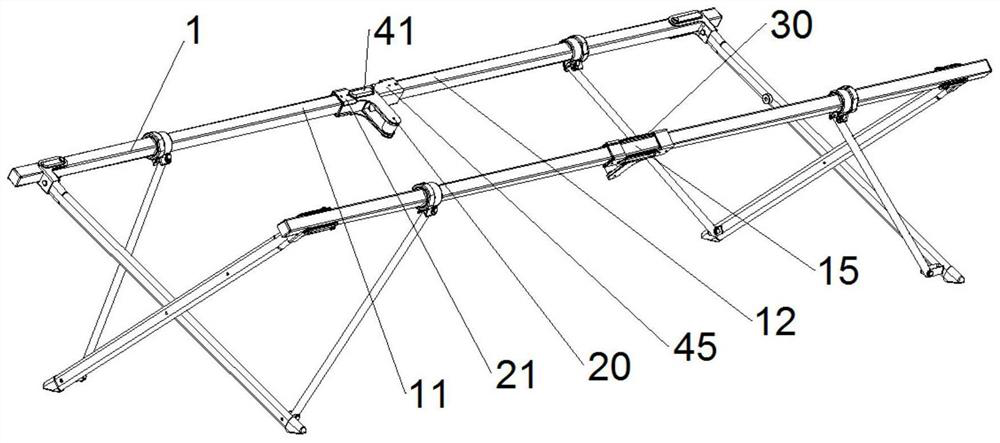
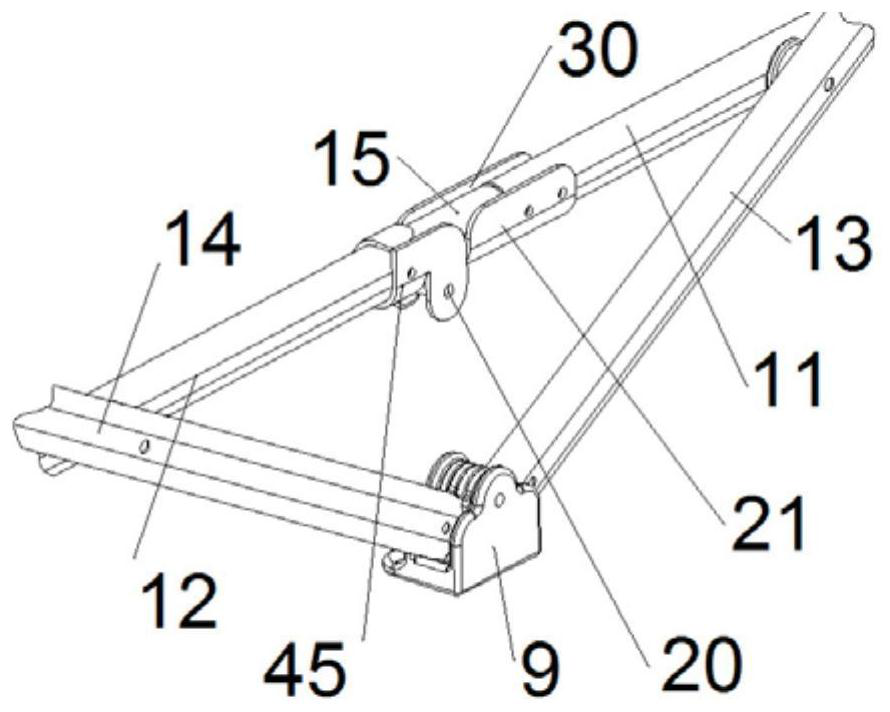
[0104] refer to Figure 1 to Figure 49 , folding product rigid hinge device, in the involved folding bed (1), folding chair (2), folding cart (3), folding pergola (4), folding table, folding hammock, folding storage cabinet, folding door, folding truss In other folding products or folding components, it includes: same-plane horizontal rigid hinge tube A (11), same-plane horizontal rigid hinge tube B (12), same-plane rigid hinge device (21, 22, 23), and also includes: same-plane Oblique intersection tube A (13), obliquely intersecting tube B on the same plane (14), oblique rigid hinged tube A on the same plane (17), oblique rigid hinged tube B on the same plane (18), and hinged joints on the same plane (45), wherein, The same plane horizontal rigid hinge tube A (11) and the same plane horizontal rigid hinge tube B (12) are hinged in the same plane, similarly, the same plane oblique rigid hinge tube A (17) and the same plane oblique rigid hinge tube B (18) Also hinged in the sa...


PUM


Abstract

The invention relates to a rigid hinge device of a folding product. The rigid hinge device comprises a coplanar rigid hinge device, a parallel plane rigid hinge device, various types of horizontal rigid hinge pipes and inclined rigid hinge pipes in the same plane, and various types of horizontal rigid hinge pipes and inclined rigid hinge pipes in the parallel plane; front clamping grooves or rear clamping grooves are formed in the coplanar rigid hinge device and the parallel plane rigid hinge device; and extension clamped sections or inner side clamped sections are simultaneously arranged on the all types of horizontal rigid hinge pipes and inclined rigid hinge pipes on the same plane and all the types of horizontal rigid hinge pipes and inclined rigid hinge pipes on the parallel plane at the rigid hinge points on the same plane and the rigid hinge points on the parallel plane. When the folding product is folded, the extension clamped sections or the inner side clamped sections fall into the front clamping grooves or the rear clamping grooves in the coplanar and parallel plane rigid hinge device and are tightly clamped, so that the folding product of a composite crossed hinge structure and the folding product of a non-crossed hinge structure are completely and rigidly hinged.

Description

technical field [0001] The invention relates to furniture and truss products, including folding chairs, folding beds, folding pergolas, folding carts, folding tables, folding hammocks, folding storage cabinets, folding doors, folding trusses and other folding products, especially composite cross furniture and trusses class folding widget. Background technique [0002] In the existing folding products or folding components, including tourism and leisure folding products, when cross hinges are used for two-dimensional or three-dimensional folding and unfolding, a single cross hinge structure is adopted, which has a high hinge Rigidity, however, in order to make the product or component folded into a smaller volume, it is necessary to use a composite cross-tube hinge, that is, when more than two sets of tubes are cross-hinged, because the hinge is a point hinge or the bonding surface of the hinge point is very small, plus The gap between the hinge holes, the rigidity of the hi...

Claims


Application Information

Patent Timeline
Patent Type & Authority Applications(China)
IPC IPC(8): F16C11/04F16C11/10
CPCF16C11/04F16C11/10
Inventor 薛勇
Owner 薛勇
Why Eureka
Try Eureka