Trapezoidal frame for line fault detection of illuminating lamp
A technology of line failure and ladder frame, applied in the direction of ladders, buildings, building structures, etc., can solve the problems of inconvenient self-balancing of the staff, easy shaking of the herringbone ladder, and inability to store detection tools, etc., to achieve convenient self-balancing and convenient detection. , to avoid the effect of abnormal rotation
- Summary
- Abstract
- Description
- Claims
- Application Information
AI Technical Summary
Problems solved by technology
Method used
Image
Examples
Embodiment 1
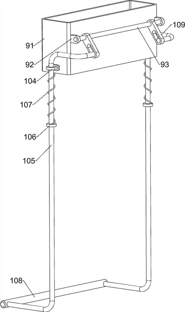
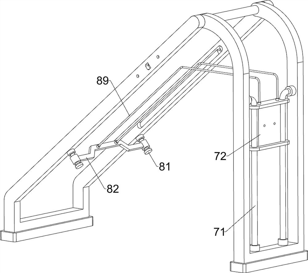
[0036] A ladder-shaped frame for detection of lighting circuit faults, such as Figure 1-8 As shown, it includes a mounting frame 1, a pedal 2, a first cross bar 3, a bracket 4, a rubber pad 5, a connecting plate 51, a sliding shaft 52, a limit assembly 6 and a support assembly 7, and the mounting frame 1 is stepped There is a row of pedals 2, the upper part of the installation frame 1 is provided with a first cross bar 3, the first cross bar 3 is provided with a support 4 in a rotating manner, the bottom of the support 4 is provided with a rubber pad 5, and the bottom of the installation frame 1 is provided with the same rubber pad 5. Both sides of the upper part of the bracket 4 are rotatably provided with connecting plates 51, and both sides of the upper part of the mounting frame 1 are slidably provided with sliding shafts 52, and the sliding shafts 52 are rotatably connected with the connecting plates 51 on the same side. 1 is provided with a limit assembly 6, and the bra...
Embodiment 2
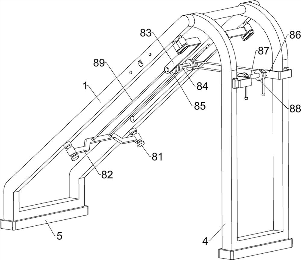
[0043] On the basis of Example 1, such as figure 1 , figure 2 , image 3 , Figure 4 , Figure 9 , Figure 10 , Figure 11 , Figure 12 , Figure 13 , Figure 14 , Figure 15 and Figure 16 As shown, a pulling assembly 8 is also included, and the pulling assembly 8 includes a positioning shaft 81, a special-shaped plate 82, a first mounting plate 83, a first rotating rod 84, a first fixed pulley 85, a second mounting plate 86, a second rotating Bar 87, the second fixed pulley 88 and backguy 89, mounting frame 1 left bottom, front and rear both sides are all provided with positioning shaft 81, are connected with special-shaped plate 82 between front and rear two positioning shafts 81, mounting frame 1 right top, front and rear both sides The first mounting plate 83 is provided, and the first rotating rod 84 is provided in rotation between the two first mounting plates 83 before and after the first rotating rod 84. The first fixed pulley 85 is provided on both sides o...
PUM
 Abstract
Description
Claims
Application Information
 - R&D Engineer
- R&D Manager
- IP Professional
- Industry Leading Data Capabilities
- Powerful AI technology
- Patent DNA Extraction
Browse by: Latest US Patents, China's latest patents, Technical Efficacy Thesaurus, Application Domain, Technology Topic, Popular Technical Reports.
© 2024 PatSnap. All rights reserved.Legal|Privacy policy|Modern Slavery Act Transparency Statement|Sitemap|About US| Contact US: help@patsnap.com


