
Capacitor pin bending and cutting device

A technology for cutting capacitors and feet, which is applied in capacitors, capacitor manufacturing, circuits, etc., can solve problems such as low safety, and achieve the effect of improving low safety and improving production efficiency

Active Publication Date: 2021-10-08
SHENZHEN SINCERITY TECH
View PDF9 Cites 0 Cited by
  • Summary
  • Abstract
  • Description
  • Claims
  • Application Information

AI Technical Summary

Problems solved by technology

[0005] In order to improve the problem of low equipment safety, the application provides a capacitor bending and cutting device

Method used


Image

  • Capacitor pin bending and cutting device
  • Capacitor pin bending and cutting device

Examples


Embodiment Construction

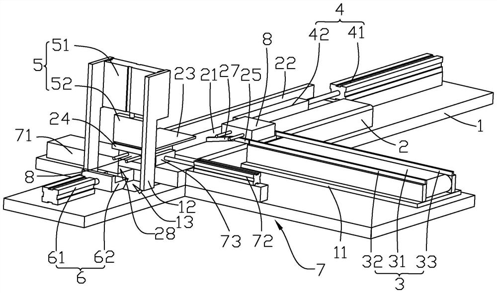
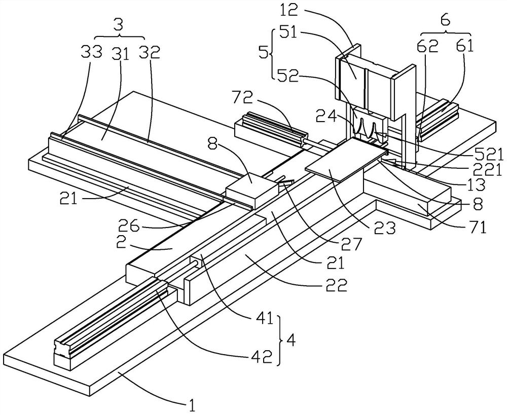
[0035] Contraction below Figure 1-2 Further detailed description of the present application.

[0036] A capacitor disclosed embodiments Cutting bending apparatus of the present application. Refer figure 1 with figure 2 , Curved legs cutting apparatus comprises a table 1, feed table 2, the conveying mechanism 3, pusher means 4, 5 the folding mechanism, the cutting mechanism 6 and the takeup device 7, feed table 2 is fixedly connected to the top surface of the table 1, cuboid feed table 2, table 2 material guiding groove defines a top surface 21, a rectangular parallelepiped guide chute 21, feed channel 21 communicates with both ends of the feed table 2, the guide chute 21 and the side surface side of the feed table 2 communication, feed table 2 and the guide chute 21 side communicating with the side plate 22 is fixedly connected with the guide chute 21 is provided with a capacitor 8, 8 sliding on the capacitor bottom chutes 21; the transport mechanism 3, pusher means 4, 5 the foldi...


PUM


Abstract

The invention discloses a capacitor pin bending and cutting device. The capacitor pin bending and cutting device comprises a workbench and a material table installed on the top face of the workbench, wherein a guide chute is formed in the top face of the material table; a capacitor is arranged in the guide chute; the capacitor is in sliding connection with the material table through the guide chute ; the guide chute is communicated with the side face of one side of the material table; a baffle is fixedly connected to the side face of one side of the material table and located on the side face of the side, communicated with the material table, of the guide chute; a top plate is fixedly connected to the top end face of the baffle; a limiting strip is fixedly connected to the end face of one end of the top plate; a lead of the capacitor extends out of the material table; a conveying mechanism used for conveying the capacitor to the material table and a pushing mechanism used for pushing the capacitor to the limiting strip are installed on the material table; a bending mechanism used for bending a capacitor lead and a cutting-off mechanism used for cutting off the capacitor lead are installed at one end of the material table; and a receiving mechanism used for conveying the processed capacitor away from the material table is installed on the material table. The capacitor pin bending and cutting device has the effect of solving the problem of low equipment safety.

Description

Technical field [0001] The present invention relates to the field of automated equipment, in particular, to a capacitor curved foot device. Background technique [0002] After the capacitor is processed, the capacitor is bent by the capacitor two leads to a certain angle, and then the two leads are truncated to meet the use of the board. [0003] In the relevant technique, the bending of the capacitor is often used by artificial bends, and then puts the capacitor onto the device, and the lead wire is cut off by artificial handbased capacitor. [0004] In response to the above-described related techniques, the inventors believe that during the truncation of the capacitor lead, it is often used by manual operation, and the manual operation is low, and when the operation is cut, it is through the hand fixed capacitor, the finger is close to the cutting tool It is easy to cover your fingers, causing a problem that the device is safe. Inventive content [0005] In order to improve th...

Claims


Application Information

Patent Timeline
Patent Type & Authority Applications(China)
IPC IPC(8): B21F11/00B21F23/00H01G13/00
CPCB21F11/00B21F23/005H01G13/00
Inventor 吴钰东吴建明王习华李江林吕小龙
Owner SHENZHEN SINCERITY TECH
Learn More