Laser recognition device and method for welding

A laser identification and welding device technology, which is applied to welding accessories, devices for providing/removing protective gas, etc., can solve the problems of short service life of shielding parts, large energy consumption of protective gas, and influence on sensor measurement accuracy, etc., to reduce heat Loss, improve heat dissipation efficiency, improve the effect of energy utilization

Active Publication Date: 2021-10-01
安徽工布智造工业科技有限公司
View PDF6 Cites 0 Cited by
  • Summary
  • Abstract
  • Description
  • Claims
  • Application Information

AI Technical Summary

Problems solved by technology

[0004] Therefore, the present invention is made in view of the above problems. The present invention provides a laser recognition device and method for welding, which solves the need that the heat and spatter generated in welding affect the measurement accuracy of the sensor and the service life of the shielding parts is not long. Frequent replacement, and the use of shielding gas for welding will consume a lot of energy and other issues

Method used


Image

  • Laser recognition device and method for welding
  • Laser recognition device and method for welding
  • Laser recognition device and method for welding

Examples


Embodiment Construction

[0031] Preferred embodiments of the present invention will be described in detail with reference to the accompanying drawings so that those embodiments can be easily realized by those having ordinary skill in the art to which the invention pertains. However, the present invention can also be realized in various forms, so the present invention is not limited to the embodiments described hereinafter. In addition, in order to describe the present invention more clearly, parts not connected with the present invention will be omitted from the drawings.

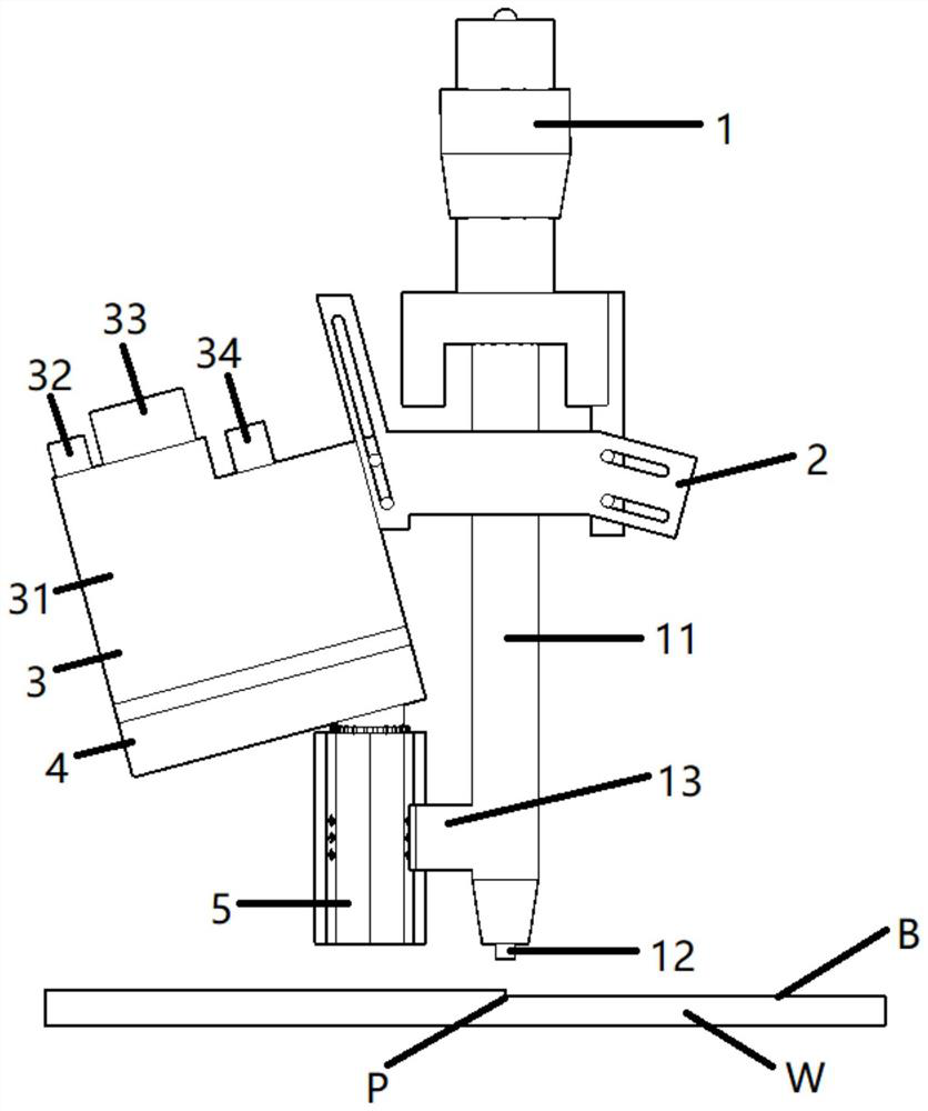
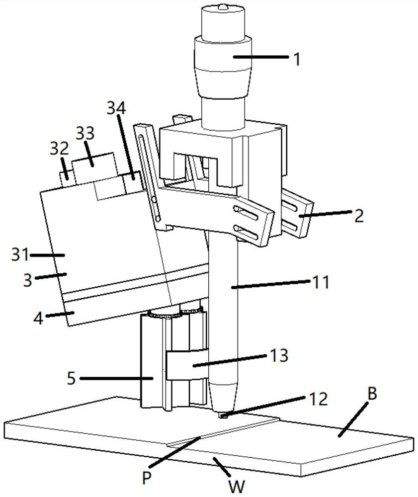
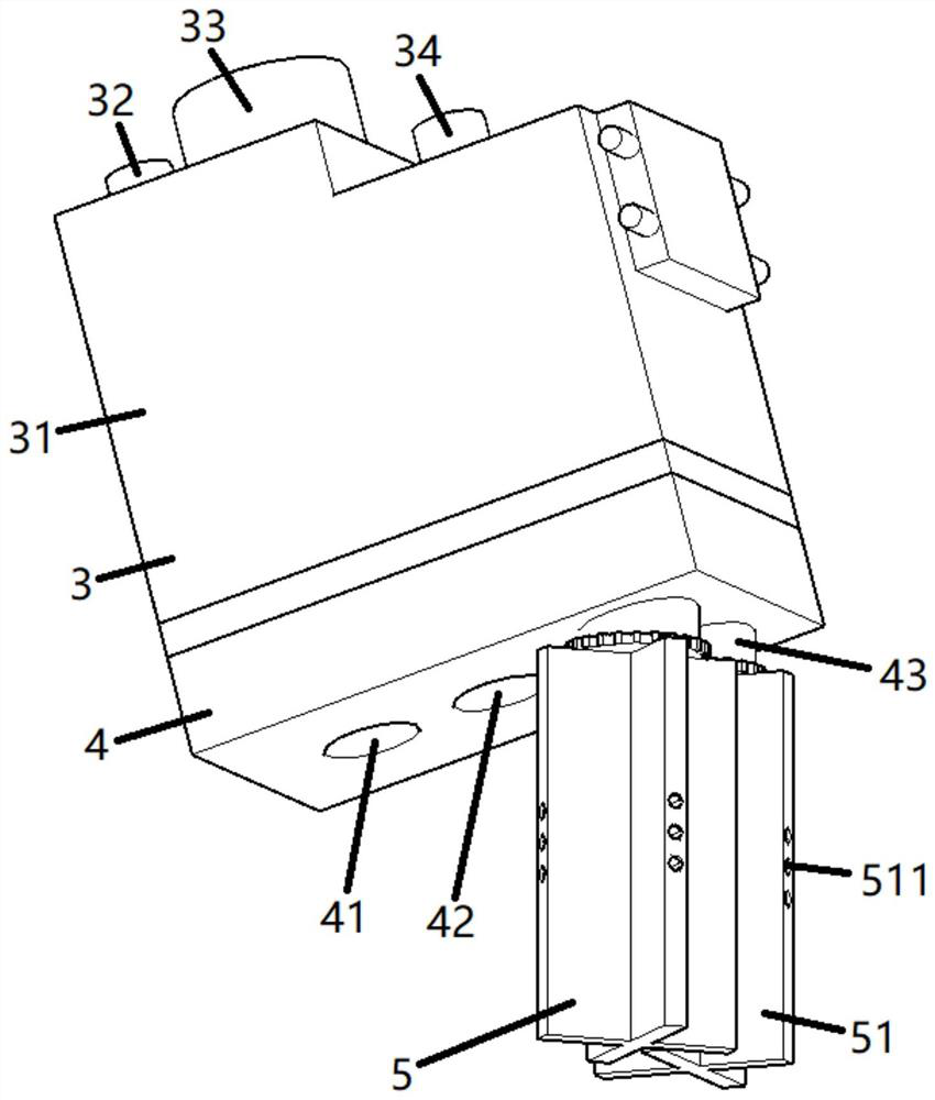
[0032] Such as figure 1 As shown, a laser identification device for welding includes: a welding device 1, a fixture 2 for installation, a sensor unit 3, a protective cover 4, and a shielding part 5;

[0033] Such as figure 1 As shown, the sensor unit 3 according to this embodiment is mounted on the welding device 1 through the jig 2; the welding wire 12 is supplied to the welding torch 11 of the welding device 1; A voltage is ap...


PUM


Abstract

The invention relates to the technical field of welding, in particular to a laser recognition device and method for welding. The laser recognition device comprises a welding device, a clamp, a sensor unit, a protective cover, a shielding part and a gas flow path, wherein the sensor unit is installed on the welding device through the clamp, a welding torch is arranged at the lower end of the welding device, a welding wire is arranged at the lower end of the welding torch, the welding torch is provided with an arc-shaped buffer plate, and a workpiece is arranged at the lower end of the welding wire.The sensor unit comprises a containing box, a gas supply port, a first connecting terminal, a second connecting terminal, a light transmitting plate, a light projection part, a detection part and a first gas flow path. By arranging a cooling gas chamber, pressures of gases entering the cooling gas chamber from two upper end runners are equalized, so that the speeds of gases exhausted from deflation holes of two shielding parts are basically the same, and therefore, the stability of the system is improved.

Description

technical field [0001] The invention relates to the field of welding, in particular to a laser recognition device and method for welding. Background technique [0002] Conventionally, when butt welding or the like is performed by arc welding or the like on workpieces such as a pair of iron plates having a groove shape, the welding torch is brought close to the workpiece (the butted groove-shaped portion). In this state, a voltage is applied between the tip of the welding wire supplied from the welding torch and the workpiece, and an arc is generated between them. In this way, the welding wire melts, the workpieces are heated and melted, and the workpieces can be welded together. [0003] When welding, the distance between the welding torch and the workpiece or the shape of the workpiece has an impact on the welding quality of the workpiece. Therefore, in the welding process of the prior art, a sensor needs to be used to measure the distance between the welding torch and the...

Claims


Application Information

Patent Timeline
Patent Type & Authority Applications(China)
IPC IPC(8): B23K9/32
CPCB23K9/32B23K9/325
Inventor 郭家友王继文侯克文王伟昌
Owner 安徽工布智造工业科技有限公司
Why Eureka
Try Eureka