Monitor
A technology of monitors and microprocessors, applied in the field of monitors, can solve problems such as insufficient modularity and internal structure chaos
- Summary
- Abstract
- Description
- Claims
- Application Information
AI Technical Summary
Problems solved by technology
Method used
Image
Examples
no. 1 example
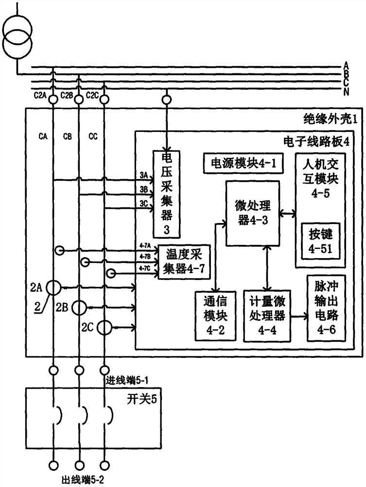
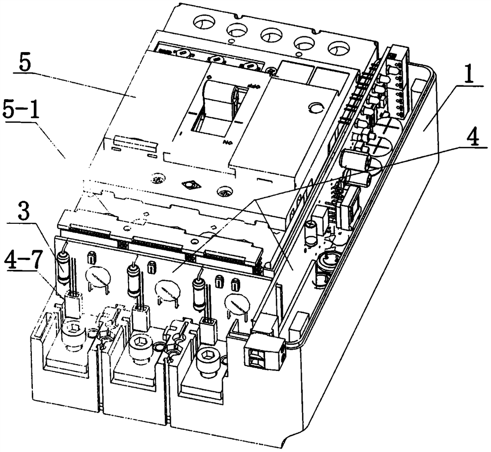
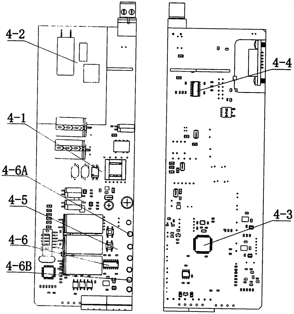
[0040] Such as Figure 1 to Figure 10As shown, this embodiment discloses a monitor, which includes an insulating housing 1, at least one current collector 2, at least one voltage collector 3, and at least one electronic circuit board 4 are arranged in the insulating housing 1 , the electronic circuit board 4 is provided with a power supply module 4-1, a communication module 4-2, a microprocessor 4-3, a measurement microprocessor 4-4 and a human-computer interaction module 4-5, and the insulating shell 1 Some are arranged on the side of the incoming line end 5-1 of the switch 5.
[0041] In this embodiment, the current collector 2 includes a first current collector 2A, a second current collector 2B and a third current collector 2C, and the first current collector 2A, the second current collector 2B and The third current collector 2C is respectively located in different poles in the insulating casing 1 of the monitor, and its inner holes 2-1 respectively pass through the main w...
no. 2 example
[0056] Such as Figure 11 , is a schematic diagram of the second embodiment of a monitor. A monitor disclosed in this embodiment includes an insulating housing 1, in which at least one current collector 2, at least one voltage collector 3, and at least one electronic circuit board 4 are arranged, and a power module 4-1 is arranged on the electronic circuit board 4. , a communication module 4-2, a microprocessor 4-3, a metering microprocessor 4-4, and a human-computer interaction module 4-5, and the insulating shell 1 is partly arranged on the outlet terminal 5-2 side of the switch 5.
[0057] The difference from the first embodiment is that the insulating casing 1 is partly arranged on the outlet terminal 5 - 2 side of the switch 5 . The advantage of the second embodiment is that the design position of the insulating shell 1 is more flexible to meet different design requirements. The insulating shell 1 can be partially arranged on the incoming line terminal 5-1 of the switch ...
no. 3 example
[0059] Such as Figure 12 , is a schematic diagram of Embodiment 3 of a monitor. A monitor disclosed in this embodiment includes an insulating housing 1, in which at least one current collector 2, at least one voltage collector 3, and at least one electronic circuit board 4 are arranged, and a power module 4-1 is arranged on the electronic circuit board 4. , a communication module 4-2, a microprocessor 4-3, a metering microprocessor 4-4, and a human-computer interaction module 4-5. The inner holes 2-1 of each current collector 2 pass through the first conductor CA, the second conductor CB and the third conductor CC respectively, and the first conductor CA, the second conductor CB and the One end of the third electrical conductor CC is directly installed and electrically connected to the switch 5, and the other end of the conductor is connected to the first cable C2A, the second cable C2B and the third cable C2C. It is characterized in that: the electronic circuit board 4 is a...
PUM
 Abstract
Description
Claims
Application Information
 - R&D
- Intellectual Property
- Life Sciences
- Materials
- Tech Scout
- Unparalleled Data Quality
- Higher Quality Content
- 60% Fewer Hallucinations
Browse by: Latest US Patents, China's latest patents, Technical Efficacy Thesaurus, Application Domain, Technology Topic, Popular Technical Reports.
© 2025 PatSnap. All rights reserved.Legal|Privacy policy|Modern Slavery Act Transparency Statement|Sitemap|About US| Contact US: help@patsnap.com


