System for enhancing brightness of projection picture

A picture and projection technology, applied in the field of backlight display, can solve problems such as insufficient projection brightness

Active Publication Date: 2021-09-24
GOERTEK OPTICAL TECH CO LTD
View PDF5 Cites 0 Cited by
  • Summary
  • Abstract
  • Description
  • Claims
  • Application Information

AI Technical Summary

Problems solved by technology

[0004] The main purpose of the present invention is to provide a system for enhancing the brightness of the projection screen, aiming to solve the technical problem of insufficient projection brightness in the prior art

Method used


Image

  • System for enhancing brightness of projection picture
  • System for enhancing brightness of projection picture
  • System for enhancing brightness of projection picture

Examples


Embodiment Construction

[0034] It should be understood that the specific embodiments described here are only used to explain the present invention, not to limit the present invention.

[0035] The following will clearly and completely describe the technical solutions in the embodiments of the present invention with reference to the accompanying drawings in the embodiments of the present invention. Obviously, the described embodiments are only part of the embodiments of the present invention, not all of them. Based on the embodiments of the present invention, all other embodiments obtained by persons of ordinary skill in the art without creative efforts fall within the protection scope of the present invention.

[0036] It should be noted that all directional indications (such as up, down, left, right, front, back...) in the embodiments of the present invention are only used to explain the relationship between the components in a certain posture (as shown in the accompanying drawings). Relative positi...


PUM


Abstract

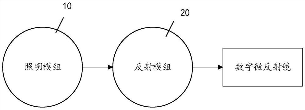
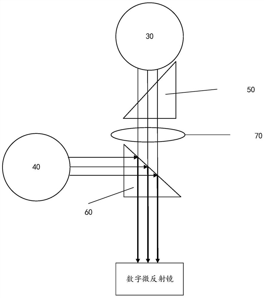
The invention discloses a system for enhancing the brightness of a projection picture, which comprises a reflection module and an illumination module. The reflection module comprises a first triangular prism, a second triangular prism and a relay lens, and the illumination module comprises a first illumination module and a second illumination module; the first emergent light of the first lighting module is perpendicular to the second emergent light of the second lighting module; the relay lens is arranged on a light path of the first emergent light and is located between the first triangular prism and the second triangular prism; the first triangular prism is located between the first illumination module and the relay lens, and any right-angle side of the first triangular prism is parallel to the first emergent light; the second triangular prism is arranged at the intersection of the first emergent light and the second emergent light, so that the second emergent light is consistent with the first emergent light in direction after being reflected by the bevel edge of the second triangular prism, the two illumination modules are converged into the same beam of light through structural reflection of the triangular prism, and the projection display brightness is improved.

Description

technical field [0001] The invention relates to the technical field of backlight display, in particular to a system for enhancing the brightness of a projected picture. Background technique [0002] Head-up display (HUD) for short, also known as parallel display system, is an airborne optical display system that first appeared on fighter jets. etc.) are projected onto the perspective mirror directly in front of the pilot's field of vision, so that when the pilot maintains a head-up state, both instrument parameters and external objects are taken into account in the same field of view. This technology has also been introduced into cars in recent years. Its function is to project important driving information such as speed and navigation to the front of the driver, so that the driver can see it without bowing or turning his head. Important driving information such as speed, navigation, etc. However, there are very few mass-produced cars equipped with this technology as stand...

Claims


Application Information

Patent Timeline
Patent Type & Authority Applications(China)
IPC IPC(8): G03B21/20G03B21/00
CPCG03B21/2066G03B21/2033G03B21/008
Inventor 丁卫涛王芳芳
Owner GOERTEK OPTICAL TECH CO LTD
Why Eureka
Try Eureka