


Quick Research
Generate reliable direction feasibility study reports for your R&D in just a few steps.

Technical Q&A
Discover and master advanced knowledge NOW. Basics, ideas, possibilities, all at once.

Find Solutions
As an expert in R&D theories, this can generate solutions to your technical problems instantly.

Evaluate Feasibility
Analyze your overall solution with one click, know your potential R&D risks in advance.

Monitor Landscape
Get weekly tech updates, stay abreast of the latest tech innovations and key insights.
Auxiliary system applied to ship navigation instrument
An auxiliary system and ship navigation technology, applied in the field of auxiliary systems of ship navigation instruments, can solve the problems of non-removable movement, inability to view the screen, shock absorption, etc., and achieve the effect of solving the problem of shock absorption and solving the problem of non-removable movement.
- Summary
- Abstract
- Description
- Claims
- Application Information
AI Technical Summary
Problems solved by technology
Method used
Image

Examples
Embodiment 2
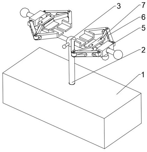
[0030] to combine Figure 1-4 As shown, based on the above-mentioned embodiment 1, the shock absorbing assembly 8 includes a movable groove 801 opened inside the base 1, a spring 802 is fixedly installed on the right side wall of the movable groove 801, and a piston A803 is fixedly installed on the end of the spring 802, and the piston A803 A803 is movably installed with a piston B805 above the sliding movable groove 801 inside the movable groove 801, and the upper surface of the piston B805 is fixedly connected with the support rod 2, and the inside of the base 1 is injected with a sealing liquid 804 between the piston A803 and the piston B805.
[0031] Based on the above mechanism, the purpose of placing the shock absorbing assembly 8 is achieved by setting the movable groove 801, the purpose of fixing the piston A803 and rebounding the piston A803 is achieved by setting the spring 802, and the limit and control of the sealing liquid 804 is achieved by setting the piston A803...
Embodiment 3
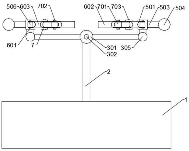
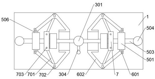
[0033] to combine Figure 1-3 As shown in and 5, based on the above-mentioned embodiment 1, the steering assembly 3 includes a steering ball housing 301 fixedly installed on the upper end of the support rod 2, the steering fixed ball (4) is rotatably installed inside the steering ball housing (301), and turns to The fixed ball (4) is fixedly connected with the upper end of the support rod (2), and the outer surface of the steering fixed ball 4 is evenly provided with a fixing hole 401, and the outer surface of the steering ball housing 301 is provided with a housing hole 302, and the inside of the steering ball housing 301 is located in the housing The relative position of the hole 302 is provided with a limit hole 303, and the inside of the housing hole 302 is inserted with a limit rod 304, and the limit rod 304 is inserted and matched with the limit hole 303 through the inside of the steering fixed ball 4, and the outer surface of the steering ball housing 301 is symmetrical....
Embodiment 4
[0036] to combine Figure 1-3 As shown in and 6, based on the above-mentioned embodiments 1 and 3, the connection assembly 5 includes two groups of connection blocks 501 fixedly installed on the upper ends of the two groups of connection rods 305 respectively. The inside of the two groups of connection blocks 501 is opened with a connection groove 502, and the connection groove 502 A movable rod 503 is slidingly inserted inside the movable rod 503, and two sets of limiting plates 7 are respectively fixed on the upper and lower sides of the inner end of the movable rod 503, and the two groups of limiting plates 7 are located on both sides of the movable rod 503 and symmetrically fixed with a rotating shaft C703 A connection ball 504 is fixedly installed on the outer end of the movable rod 503, a support plate A505 is fixedly installed on the inner end of the movable rod 503, and fixed blocks 506 are fixedly installed on both sides of the connecting block 501.
[0037] Based on ...
PUM
 Abstract
Description
Claims
Application Information
 - R&D Engineer
- R&D Manager
- IP Professional
- Industry Leading Data Capabilities
- Powerful AI technology
- Patent DNA Extraction
Browse by: Latest US Patents, China's latest patents, Technical Efficacy Thesaurus, Application Domain, Technology Topic, Popular Technical Reports.
© 2024 PatSnap. All rights reserved.Legal|Privacy policy|Modern Slavery Act Transparency Statement|Sitemap|About US| Contact US: help@patsnap.com