An Auxiliary System Applied to Ship Navigation Instruments
An auxiliary system and ship navigation technology, applied in the auxiliary system field of ship navigation instruments, can solve the problems of non-detachable movement, inability to view the screen, shock absorption, etc., and achieve the effect of solving the problem of shock absorption and non-detachable movement
- Summary
- Abstract
- Description
- Claims
- Application Information
AI Technical Summary
Problems solved by technology
Method used
Image

Examples
Embodiment 2
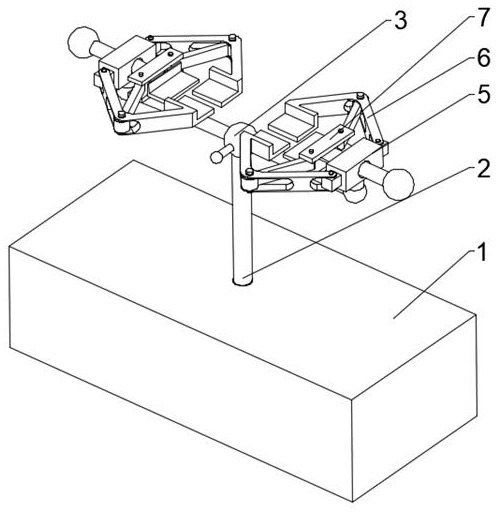
[0030] Combine Figure 1-4 As shown, based on the above-described Embodiment 1, the damping assembly 8 includes a movable groove 801 inserted inside the base 1, and the right side wall of the movable groove 801 is fixedly mounted, and the end of the spring 802 is fixedly mounted, and the piston A803 is mounted, and the piston The A803 is attached to the upper surface of the movable groove 801 internally sliding the movable groove 801, and the upper surface of the piston B805 is fixed to the support rod 2, and the inner portion of the base 1 is injecting a sealing liquid 804 between the piston A803 and the piston B805.
[0031] Based on the above mechanism, by providing the movable groove 801, the purpose of placing the damper assembly 8 is provided, by providing the spring 802 to achieve the purpose of the fixed piston A803 rebound piston A803, by providing the piston A803, thereby achieving a defined control seal liquid 804 Objective To set the sealing liquid 804 to achieve the pu...
Embodiment 3
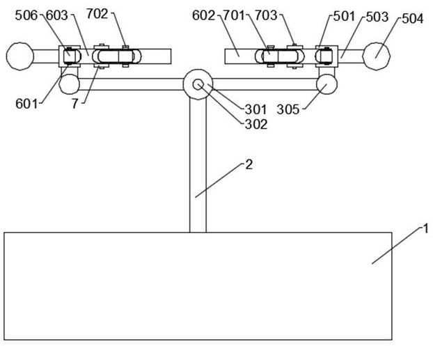
[0033] Combine Figure 1-3 From the above-described embodiment, the steering assembly 3 includes a steering ball housing 301 fixed to the upper end of the support rod 2, the steering fixation ball (4) rotates inside the steering ball housing (301), and steering The fixing ball (4) is fixed to the upper end of the support rod (2), and the outer surface of the steering fixing ball 4 is uniformly opened with a fixing hole 401, and the outer surface of the steering ball housing 301 is opened, and the inside of the steering ball housing 301 is located in the outer casing. The opposing position of the hole 302 is opened, and the inner portion of the outer casing hole 302 is inserted, and the limit lever 304 is inserted with the limit hole 303 and the outer surface of the ball housing 301 by the steering fixing ball 4. The connecting rod 305 is fixedly mounted.
[0034] Based on the above mechanism, by providing the steering ball housing 301, the purpose of connecting the support rod 2 an...
Embodiment 4
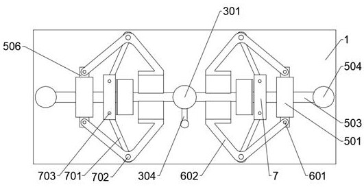
[0036] Combine Figure 1-3 As shown in FIG. The internal slide is inserted with active rod 503, and the two sets of restricted plates 7 are fixed to the inner end portion of the movable rod 503, and the two sets of restricted plates 7 are located on both sides of the movable rod 503, fixed axis C703. The outer end portion of the active rod 503 is fixedly mounted having a connection ball 504, and the inner end portion of the movable rod 503 is fixedly mounted having a support plate A505, and both sides of the connecting block 501 are fixedly mounted having a fixed block 506.
[0037] Based on the above mechanism, the purpose of connecting the steering assembly 3 and the claw 602 is provided by setting the connection block 501, by providing the active rod 503 to achieve the purpose of the control clamp 602, by setting the connecting ball 504, thereby reaching The active rod 503 and the purpose of the handle are provided by providing the support plate A505, thereby achieving the purpo...
PUM
 Abstract
Description
Claims
Application Information
 - R&D
- Intellectual Property
- Life Sciences
- Materials
- Tech Scout
- Unparalleled Data Quality
- Higher Quality Content
- 60% Fewer Hallucinations
Browse by: Latest US Patents, China's latest patents, Technical Efficacy Thesaurus, Application Domain, Technology Topic, Popular Technical Reports.
© 2025 PatSnap. All rights reserved.Legal|Privacy policy|Modern Slavery Act Transparency Statement|Sitemap|About US| Contact US: help@patsnap.com