Battery swap station

A technology for swapping stations and power grids, which is applied in the field of swapping stations and can solve the problems of inflexible charging methods, inability to meet user electricity demand, and low stability and reliability.

Active Publication Date: 2021-09-21
HUANENG CLEAN ENERGY RES INST
View PDF5 Cites 1 Cited by
  • Summary
  • Abstract
  • Description
  • Claims
  • Application Information

AI Technical Summary

Problems solved by technology

In the prior art, the electrical equipment can be charged through the power station. However, the charging method of the existing power station is not flexible enough, and the stability and reliability of the power supply of the power station are low, which cannot meet the electricity demand of users.

Method used


Image

  • Battery swap station
  • Battery swap station

Examples


Embodiment approach

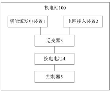
[0031] Method 1. The inverter 3 can only convert the first AC power into the first DC power of the third voltage level based on the charging command, that is, only the first AC power generated by the new energy power generation device 1 is used to replace the battery 4 at this time. to charge.

[0032] Method 2. The inverter 3 can convert both the first AC power and the second AC power into the first DC power of the third voltage level based on the charging command, that is, the first AC generated by the new energy power generation device 1 can be used at the same time. The electric energy, as well as the second AC electric energy output by the grid, charges the swap battery 4 .

[0033] Method 3: The inverter 3 can only convert the second AC power into the first DC power of the third voltage level based on the charging command, that is, only the second AC power output from the grid is used to charge the swap battery 4 at this time.

[0034] In the embodiment of the present d...


PUM


Abstract

The invention discloses a battery swap station. The battery swap station comprises a new energy power generation device, a power grid access device, an inverter, a battery swap battery and a controller, wherein the new energy power generation device is used for converting new energy into first alternating-current electric energy of a first voltage level and outputting the first alternating-current electric energy; the power grid access device is used for receiving second alternating-current electric energy of a second voltage level from the power grid and outputting the second alternating-current electric energy; the controller is used for sending a charging instruction to the inverter, and the inverter can convert at least one of the first alternating-current electric energy and the second alternating-current electric energy into first direct-current electric energy of a third voltage level based on the charging instruction and charge the battery swap battery through the first direct-current electric energy. Therefore, the battery swap station comprises the new energy power generation device and the power grid access device, alternating-current electric energy generated by the new energy power generation device and alternating-current electric energy generated by the power grid can be combined for use, the charging mode is more flexible, the power supply stability and reliability of the battery swap station are improved, and the power utilization requirement of a user can be met.

Description

technical field [0001] The invention relates to the technical field of charging, in particular to a power station. Background technique [0002] At present, electric energy has been widely used in people's daily life. For example, sweeping robots, electric kettles, and induction cookers in household appliances are convenient and fast, which can greatly reduce people's housework burden. less pollution. In the prior art, the electrical equipment can be charged through the power exchange station. However, the charging method of the existing power exchange station is not flexible enough, and the stability and reliability of the power supply of the power exchange station are low, which cannot meet the electricity demand of users. Contents of the invention [0003] The present invention aims to solve one of the technical problems in the above-mentioned technologies at least to a certain extent. [0004] Therefore, the first purpose of the present invention is to propose a powe...

Claims


Application Information

Patent Timeline
Patent Type & Authority Applications(China)
IPC IPC(8): H02J7/02H02J7/04H02J3/00B60L53/80B60L53/50B60L53/51B60L53/52B60L53/53
CPCH02J7/02H02J7/04H02J7/00712H02J7/0048H02J7/007188H02J3/007B60L53/80B60L53/50B60L53/51B60L53/52B60L53/53H02J2300/20H02J2300/22H02J2300/28Y02T10/70Y02T10/72Y02T10/7072Y02T90/12
Inventor 刘大为姚帅马满堂李昊朱连峻周科刘明义裴杰曹传钊朱勇曹曦徐若晨
Owner HUANENG CLEAN ENERGY RES INST
Why Eureka
Try Eureka