
Integrated clean room air purification system and control method

An air purification system and purification system technology, which is applied in air conditioning systems, heating methods, space heating and ventilation, etc., to achieve low wind resistance, reduce energy consumption, and achieve low cost effects

Active Publication Date: 2022-05-27
武汉华康世纪医疗股份有限公司
View PDF8 Cites 1 Cited by
  • Summary
  • Abstract
  • Description
  • Claims
  • Application Information

AI Technical Summary

Problems solved by technology

However, the above solutions are difficult to provide clean air that meets the requirements of temperature, humidity and cleanliness within the allowable range of energy consumption.

Method used


Image

  • Integrated clean room air purification system and control method
  • Integrated clean room air purification system and control method
  • Integrated clean room air purification system and control method

Examples


Embodiment 1

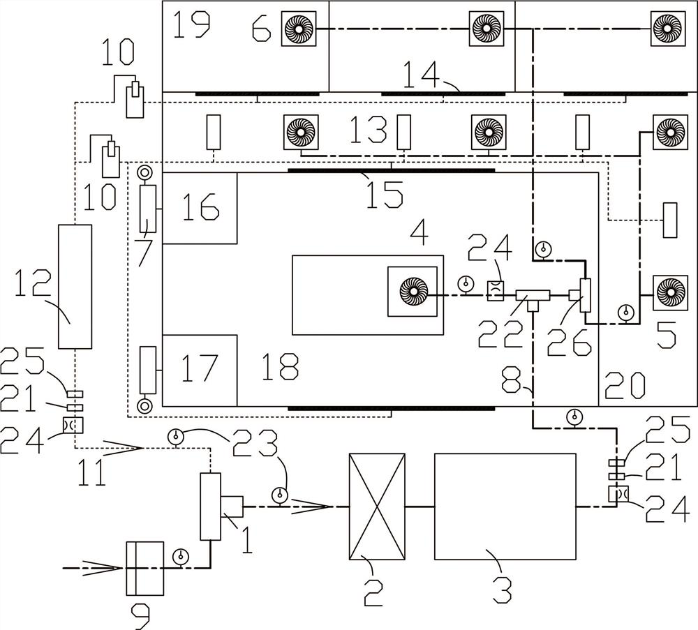
[0049] like figure 1 , an integrated clean room air purification system, which includes a fresh air unit 9, an air inlet distribution valve 1, an air purification system 2 and a circulation unit 3;

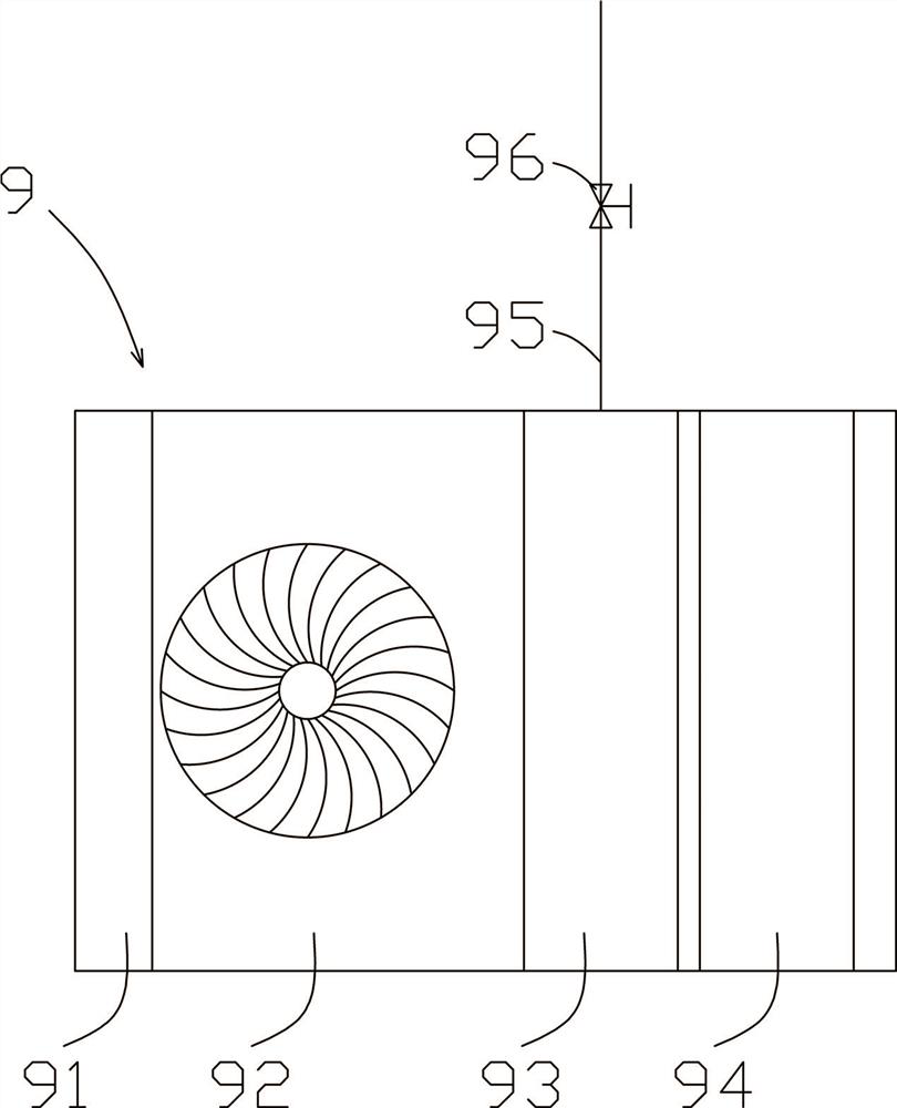
[0050] The structure of the fresh air unit 9 is as follows figure 2 As shown in the figure, a filter device 91 is provided at the inlet position, and the intake air is pretreated first. The filter device 91 preferably adopts an F6 medium-efficiency filter or other filter with lower wind resistance according to the air quality. The fresh air unit 9 is also provided with a fresh air fan 92, a temperature regulator 93 and a humidity regulator 94. The temperature regulator 93 preferably adopts an air energy temperature regulator, and is supplemented by an auxiliary heating system, such as electric auxiliary heating, or an additional heating water pipe 95. Steam heating pipes, etc., an opening adjustment valve 96 is provided on the heating water pipe 95 or the steam heating pipe, and...

Embodiment 2

[0077] A control method using the above-mentioned integrated clean room air purification system, comprising the following steps:

[0078] S1. Humidity priority control is adopted. Under summer conditions, the fresh air is cooled and dehumidified by the fresh air unit 9 and then mixed with the return air from the return air pipeline 11, and is cooled or heated to the design air supply temperature in the circulation unit 3 for a second time. back air;

[0079] Under winter conditions, when the outdoor fresh air is lower than 5°C, the fresh air is preheated to 5°C by the fresh air unit 9, heated to the set temperature value by the heat coil in the fresh air unit, and sent to the circulation unit 3 and the return air. After mixing, it is heated by the hot water coil in the circulating unit for a second time, and then humidified by the humidifier until the temperature and humidity meet the setting and then supply air;

[0080] S2. Compare the pressure and air flow rate of the oper...


PUM


Abstract

The invention provides an integrated clean room air purification system and control method, which includes a fresh air unit, an air inlet distribution valve, an air purification system and a circulation unit; the fresh air unit and the return air pipeline are respectively communicated with the distribution port of the inlet air distribution valve , the main air outlet of the air inlet distribution valve is connected with the air purification system, the air purification system is connected with the circulation unit; the circulation unit is connected with the air supply device of the clean room, and the clean room is connected with the return air pipeline; The air intake ratio of the return air duct. The present invention has a higher degree of automation, lowers the redundancy of the system, lowers the realization cost, and greatly reduces energy consumption. The control method of the present invention can perform high-efficiency automatic control on the humidity, temperature, pressure and flow rate of the air supplied to the clean room, and can realize the pressure and pressure of the key clean room through automatic control of the air inlet distribution valve and the air distribution valve. Fast response to flow regulation.

Description

technical field [0001] The invention relates to the field of clean room air treatment, in particular to an integrated clean room air purification system and a control method. Background technique [0002] In medical institutions, air quality requirements are more stringent. my country's national standard "Hospital Clean Operating Department Construction Standards" has been implemented since October 1, 2000. The "Standard" divides clean rooms into 4 grades. Article 29 of "Hospital Clean Operating Department Construction Standards" stipulates that "Class I, II, and III clean laminar flow operating rooms should adopt a local centralized air supply method, and the area of ​​the centralized air supply outlets, that is, the size of the operating area, should be consistent with the level of the laminar flow operating room. suitable, not less than 6.2 m for class I 2 (The one dedicated to the head is not less than 1.4 m 2 ), class II is not less than 4.6 m 2 , Class III not le...

Claims


Application Information

Patent Timeline
Patent Type & Authority Patents(China)
IPC IPC(8): F24F3/167F24F8/15F24F8/192F24F8/22F24F8/24F24F8/10F24F8/20F24F11/89F24F11/54F24F11/64F24F11/74F24F13/28
CPCF24F3/167F24F8/15F24F8/192F24F8/22F24F8/24F24F8/10F24F8/20F24F11/89F24F11/54F24F11/64F24F11/74F24F13/28
Inventor 李芳芳杨龙陈雨沛曹彩霞袁芳玲
Owner 武汉华康世纪医疗股份有限公司
Learn More