Bidirectional speed bump for speed-limiting road

A deceleration belt and two-way technology, applied in the field of rail transit, can solve problems such as adverse effects on drivers and passengers, limited deceleration effect, and reduced comfort, so as to avoid partial softening or even melting, prolong service life, and improve comfort.

Inactive Publication Date: 2021-09-17
张玲
View PDF0 Cites 1 Cited by
  • Summary
  • Abstract
  • Description
  • Claims
  • Application Information

AI Technical Summary

Problems solved by technology

[0003] But the existing speed bumps also have the following deficiencies in actual use: First, although the existing speed bumps are made of solid rubber, most of them are fixed on the road surface by steel nails. When this speed bump is in use, due to There is a certain interval between the steel nails, which causes the lateral force generated when the car is driving enough to the speed bump to tear the speed bump. After a long time, the speed bump is prone to damage or even incompleteness, resulting in Only the steel nails are left in place, which may puncture the tires of the car when the car passes quickly, which will easily cause adverse effects on the driver and passengers; Fast-moving vehicles cause a feeling of frustration, reminding the driver to slow down, and its own hardness is also relatively large. It also has a strong deceleration effect on slow-moving motor vehicles and non-motor vehicles, making slow-moving vehicles more comfortable. Decline, and for faster vehicles, the deceleration effect is more limited

Method used


Image

  • Bidirectional speed bump for speed-limiting road
  • Bidirectional speed bump for speed-limiting road
  • Bidirectional speed bump for speed-limiting road

Examples


Embodiment Construction

[0021] The following will clearly and completely describe the technical solutions in the embodiments of the present invention with reference to the accompanying drawings in the embodiments of the present invention. Obviously, the described embodiments are only some, not all, embodiments of the present invention. Based on the embodiments of the present invention, all other embodiments obtained by persons of ordinary skill in the art without making creative efforts belong to the protection scope of the present invention.

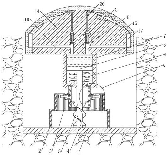
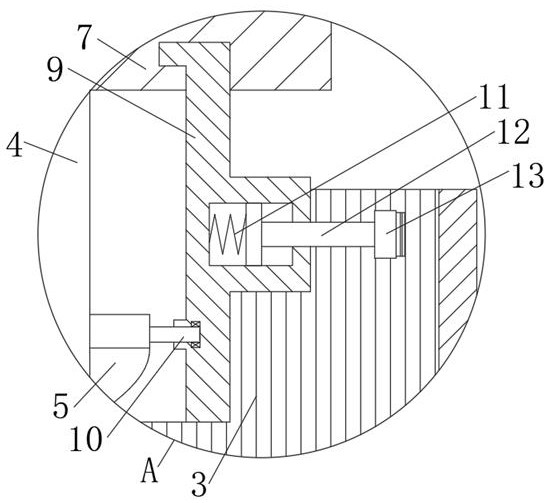
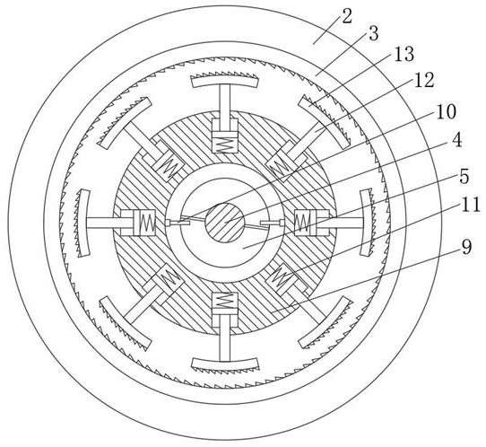
[0022] see Figure 1-7 , a two-way deceleration belt for speed-limited roads, comprising a base 1, several groups of support seats 2 are fixedly connected to the outside of the middle part of the upper end of the base 1, the upper end of the support seat 2 is fixedly connected to an inner ring gear 3, and the middle part of the upper end of the base 1 is fixedly connected to There is a support rod 4, the side of the bottom of the support rod 4 is fixedly conne...


PUM


Abstract

The invention relates to the technical field of rail transit, and discloses a bidirectional speed bump for a speed-limiting road. The bidirectional speed bump comprises a base, the outer side of the middle part of the upper end of the base is fixedly connected with a plurality of groups of supporting seats, and the upper ends of the supporting seats are fixedly connected with inner gear rings. Through the arrangement of a sleeve, a supporting rod, a rotating body and the inner gear rings, when an automobile runs on the speed bump at a too high speed, a main body moves downwards quickly under the rolling of wheels, the rotating body rotates quickly, helical teeth of the clamping blocks are meshed with helical teeth on the inner sides of the inner gear rings, the rotating body is clamped, and the main body does not descend any more, so the running automobile generates obvious vibration when passing through the speed bump, the driver is reminded to drive at a lowered speed, when the automobile runs on the speed bump at a low speed, the rotating body rotates slowly during descending, and the clamping block is thrown out, so that the main body can descend continuously, the automobile runs through the deceleration strip more stably and comfortably, and the comfort of people in the deceleration strip lifting process is improved.

Description

technical field [0001] The invention relates to the technical field of rail transit, in particular to a two-way deceleration belt for speed-limited roads. Background technique [0002] Speed ​​bumps, also called speed bumps, are traffic facilities installed on highways to slow down passing vehicles. The shape is generally a strip with arc bulges, and there are also dots; the material is mainly rubber, and there are also metals; generally yellow and black are used to attract visual attention, and the road surface is slightly arched to achieve the purpose of vehicle deceleration. It is generally installed on highway crossings, industrial and mining enterprises, schools, residential quarters, etc., where vehicles need to slow down and where traffic accidents are likely to occur. It is a new type of special traffic safety setting for reducing the speed of motor vehicles and non-motor vehicles. [0003] But the existing speed bumps also have the following deficiencies in actual ...

Claims


Application Information

Patent Timeline
IPC IPC(8): E01F9/529F16F15/08
CPCE01F9/529F16F15/08
Inventor 张玲
Owner 张玲
Why Eureka
Try Eureka