Valve clamping system

A technology of valves and clips, applied in the direction of heart valves, valve rings, etc., can solve the problems of difficult clamping, atrium and chord damage, etc.

Inactive Publication Date: 2021-09-10
SHANGHAI SHENQI MEDICAL TECH CO LTD
View PDF0 Cites 1 Cited by
  • Summary
  • Abstract
  • Description
  • Claims
  • Application Information

AI Technical Summary

Problems solved by technology

However, during the clamping process of the valve leaflets, the two clips of the valve clamp are always in a state of opening and closing with a large range and force, which is difficult to clamp, and may cause damage to the atrium and chordae tendineae during the operation. risk

Method used


Image

  • Valve clamping system
  • Valve clamping system
  • Valve clamping system

Examples


Embodiment 1

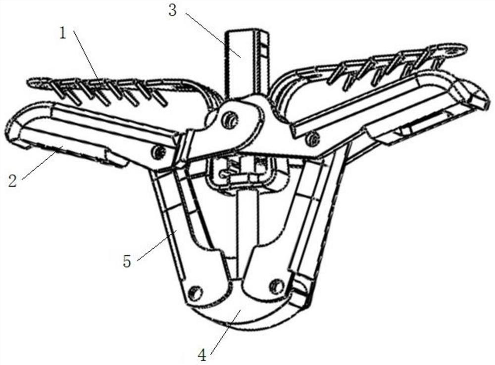
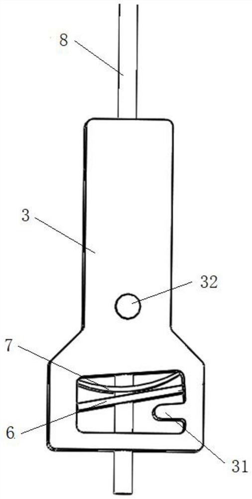
[0036] like Figure 1 to 4 , The present embodiment provides a valve clamping system, comprising an adjustment mechanism and a locking mechanism. Wherein the adjusting mechanism comprises a clip proximal end, the distal end of the clip 2, the center of the base 3 and the base body, a proximal end of the clip the clip base to the central body 3, and the proximal end of the clip 1 has elasticity, the distal end of clip 2 rotatably attached to the central body and the base body base 3, toward or away from the proximal end to a clip, having a central seat body receiving chamber 3, the center of the seat body is provided with drill holes on opposite side walls 3; locking mechanism comprises a fixing piece A6, B7 fixing piece, the push rod 8 and 9 the control member, and a fixing piece fixing piece A6 B7 against each other is provided in the receiving chamber, the push rod 8 is located in receiving chamber and through the fixing piece and the fixing piece A6 B7 is connected to the a base...

Embodiment 2

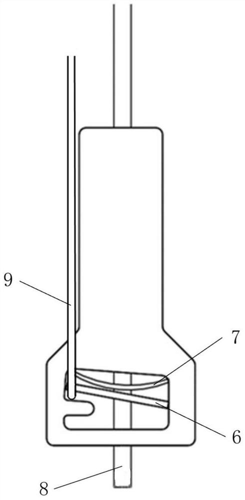
[0053] The present embodiment discloses a clamping system valve, the valve according to the present embodiment a clamping system in the embodiment of the valve clamping system embodiment except that: The Figure 5 with Image 6 , At least a fixing piece of shrapnel B7, B7 fixing piece is configured to cause the fixing piece A6 against the stopper projection 31, and in the first position, the control member 9 away from the stopper projection 31 of a push rod 8 bypassing the side fixing piece and the fixing piece A6 B7, and pulls the control member 9 is not capable of fixing sheet A6 in the first position. Alternatively, the fixing piece and the fixing piece A6 B7 are shrapnel, but when the fixing piece A6 elastic force of gravity and the applied B7 fixing piece, different from the embodiment example 1, such as Figure 5 , In relaxing the control member 9, the fixing piece can not be placed horizontally A6 receiving cavity, but is pressed against the fixing piece B7 first position, whe...


PUM

PropertyMeasurementUnit
Wire diameteraaaaaaaaaa
Maximum radiusaaaaaaaaaa

Abstract

The invention relates to the field of medical instruments, and discloses a valve clamping system. The valve clamping system comprises an adjusting mechanism and a locking mechanism. The adjusting mechanism comprises near-end clamping pieces, far-end clamping pieces, a central seat body and a base body, the near-end clamping pieces are clamped to the central seat body, the near-end clamping pieces have elasticity, the far-end clamping pieces are rotatably connected to the central seat body and the base body so as to be close to or far away from the near-end clamping pieces. The locking mechanism comprises a fixing piece A, a fixing piece B, a pushing rod and a control piece, the central seat body is provided with a containing cavity, the fixing piece A and the fixing piece B abut against each other and are clamped in the containing cavity, the pushing rod penetrates through the fixing piece A and the fixing piece B to be connected to the base body, opposite penetrating holes are further formed in the side wall of the center base body, and the control piece can pass through the penetrating holes and bypass the fixing piece A and the fixing piece B from any side of the pushing rod. The control piece and the fixing piece B are used for adjusting the position of the fixing piece A in the containing cavity, so that stable clamping of valve leaflets is achieved. The valve clamping system is simple to operate, and surgical risks can be reduced.

Description

Technical field [0001] The present invention relates to the field of medical devices, particularly to a valve clamping system. Background technique [0002] Mitral regurgitation is the most common heart valve disease, surgical valve repair or replacement surgery is considered the standard treatment for the disease, has been shown to relieve symptoms and prolong its life, therefore, the development of minimally invasive, low risk mitral regurgitation intervention instrument has a huge social and market demand. [0003] The current technology is based on intervention valve edge margin of the principle operation of the valve, the valve needs to be conveyed to the clamp mitral valve, through the sandwiching of the mitral valve contracts relatively open front and posterior leaflets of the clip, so that the two anterior lobe and the posterior leaflet cusps fixed, so as to reduce the gap leaflet, the purpose of reducing mitral regurgitation. The leaflets during clamping, the two clips c...

Claims


Application Information

Patent Timeline
IPC IPC(8): A61F2/24
CPCA61F2/2442A61F2/246A61F2/2466
Inventor 王森宋睿王智琛戴志豪李振宇黄中嵘
Owner SHANGHAI SHENQI MEDICAL TECH CO LTD
Why Eureka
Try Eureka