Stacking and discharging mechanism for storage and using method

A palletizing and warehousing technology, applied in the field of palletizing and unloading mechanism for warehousing, can solve problems such as product falling and product damage

Inactive Publication Date: 2021-09-07
马青青
View PDF0 Cites 0 Cited by
  • Summary
  • Abstract
  • Description
  • Claims
  • Application Information

AI Technical Summary

Problems solved by technology

[0002] The palletizing and unloading mechanical device is the product of the organic combination of machinery and computer programs, which provides higher production efficiency for modern production. The palletizing and unloading mechanical device has a wide range of applications in the palletizing industry. The palletizing and unloading mechanical device It greatly saves labor and space. The palletizing and unloading mechanical device uses the steps of computer programming to stack and push items through the mechanical arm. The process of clamping and stacking the palletizing and unloading mechanical device is the loading and unloading For the actual operation of unloading, the existing palletizing unloading mechanical device installs different end-of-arm tools on the arm end of the mechanical arm, such as vacuum grippers, flipping grippers and clamping grippers, through the grippers, that is, palletizing The loading and unloading device of the unloading mechanical device clamps and stacks the articles. However, most of the existing palletizing unloading mechanical devices grab the product through the gripper. Not only often the product falls, but also often due to The problem of excessive force on the gripper and damage to the product

Method used


Image

  • Stacking and discharging mechanism for storage and using method
  • Stacking and discharging mechanism for storage and using method
  • Stacking and discharging mechanism for storage and using method

Examples


Embodiment 1

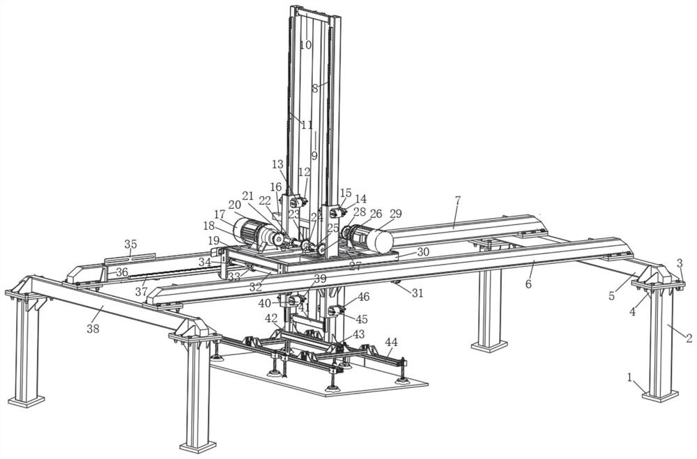
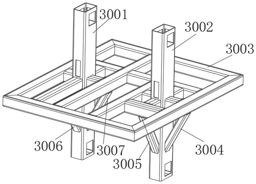
[0038] Such as Figure 1-9As shown, the stacking and unloading mechanism for storage includes a pad 1, a support leg 2, a connecting plate 3, a triangular support plate 4, a first vertical beam 5, a first cross beam 7, a first vertical rack 8, and a central column 9 , the second vertical rack 11 and the first side wheel 13, the upper end of the cushion block 1 is provided with a support leg 2, the upper end of the support leg 2 is provided with a connecting plate 3, and one end of the connecting plate 3 is provided with a triangular support plate 4, the triangular support plate 4 The upper end of the support plate 4 is provided with a first vertical beam 5, the upper end of the first vertical beam 5 is provided with a second beam 6, one end of the second beam 6 is provided with a first beam 7, and the upper end of the first beam 7 is provided with a first beam. Vertical rack 8, one end of the first vertical rack 8 is provided with a central column 9, one end of the central col...

Embodiment 2

[0048] The method of using the palletizing and unloading mechanism for storage, the steps of the method are as follows:

[0049] Step 1: first connect the palletizing and unloading mechanism for storage with an external power supply, and then drive the rotation of the first driving motor 17 and the second driving motor 29 at one end of the palletizing and unloading mechanism for storage through the external power supply. The rotation of the first driving motor 17 and the second driving motor 29 provides strong power support for the product palletizing work of the palletizing and unloading mechanism for the warehouse;

[0050] Step 2: The rotation of the first driving motor 17 further drives the rotation of the first gear 20 at one end, while the first gear 20 rotates, it further drives the rotation of the second gear 21 at one end, and the rotation of the second gear 21 drives the rotation of the second gear 21 at one end. The rotation of a driving rod 25, the first driving ro...

Embodiment 3

[0054]Working principle: firstly, connect the palletizing and unloading mechanism for storage with an external power supply, and then drive the rotation of the first drive motor 17 and the second drive motor 29 at one end of the palletizing and unloading mechanism for storage through the external power supply. The rotation of a driving motor 17 further drives the rotation of the first gear 20 at one end, and the first gear 20 further drives the rotation of the second gear 21 at one end while rotating, and the rotation of the second gear 21 then drives the rotation of the first drive rod 25 at one end. Rotate, and then drive the rotation of the third gear 23 and the fourth gear 26 at one end while the first drive rod 25 rotates, and then drive the second vertical rack 11 at one end to move up and down through the rotation of the second gear 21, and move up and down through the fourth gear 26 The rotation further drives the first vertical rack 8 at one end to move up and down. Wh...


PUM


Abstract

The stacking and discharging mechanism comprises a cushion block, supporting legs, a connecting plate, a triangular supporting plate, a first vertical beam, a first cross beam, a second vertical rack and a first side edge wheel, the supporting legs are arranged at the upper end of the cushion block, the connecting plate is arranged at the upper ends of the supporting legs, and the triangular supporting plate is arranged at one end of the connecting plate;the upper end of the triangular supporting plate is provided with a first vertical beam, the upper end of the first vertical beam is provided with a second cross beam, one end of the second cross beam is provided with a first cross beam, the upper end of the first cross beam is provided with a first vertical rack, one end of the first vertical rack is provided with a central column, one end of the central column is provided with an upper supporting plate, and one end of the upper supporting plate is provided with a second vertical rack.A first movable clamping block is arranged at the lower end of the second vertical rack, a first side wheel is arranged at one end of the first movable clamping block, and a second movable clamping block is arranged at one end of the first side wheel;the stacking and discharging mechanism for storage has the advantages that products are not prone to falling off and being damaged.

Description

technical field [0001] The invention relates to the technical field of storage management and operation equipment, in particular to a palletizing and unloading mechanism for storage, and more specifically to a palletizing and unloading mechanism for storage and a use method. Background technique [0002] The palletizing and unloading mechanical device is the product of the organic combination of machinery and computer programs, which provides higher production efficiency for modern production. The palletizing and unloading mechanical device has a wide range of applications in the palletizing industry. The palletizing and unloading mechanical device It greatly saves labor and space. The palletizing and unloading mechanical device uses the steps of computer programming to stack and push items through the mechanical arm. The process of clamping and stacking the palletizing and unloading mechanical device is the loading and unloading For the actual operation of unloading, the ex...

Claims


Application Information

Patent Timeline
Patent Type & Authority Applications(China)
IPC IPC(8): B65G57/04B65G61/00B65G57/00
CPCB65G57/04B65G61/00B65G57/00
Inventor 马青青
Owner 马青青
Why Eureka
Try Eureka