
Grabbing device for intelligent manufacturing of engineering equipment

A technology of intelligent manufacturing and grabbing devices, applied in the field of mechanical devices, can solve the problems of unsatisfactory practicability, inability to place, move or assemble parts, etc., and achieve the effect of strong practicability, precise position adjustment and excellent use effect

Inactive Publication Date: 2021-09-07
江苏极上建设有限公司
View PDF7 Cites 1 Cited by
  • Summary
  • Abstract
  • Description
  • Claims
  • Application Information

AI Technical Summary

Problems solved by technology

Although the grabbing devices disclosed in the above two utility model patents can grab parts during use, the premise of grabbing is that the parts are accurately placed at the target position, and the grabbing device cannot Arranging, moving or assembling parts on 360° makes it less practical

Method used


Image

  • Grabbing device for intelligent manufacturing of engineering equipment
  • Grabbing device for intelligent manufacturing of engineering equipment
  • Grabbing device for intelligent manufacturing of engineering equipment

Examples


Embodiment 1

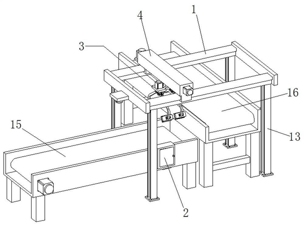
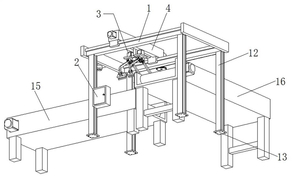
[0038]This embodiment 1 discloses a grabbing device for intelligent manufacturing of engineering equipment, refer to the attached figure 1 And attached figure 2 , its main components include horizontal rails 1, electrical cabinets 2, and grabbing mechanisms 3 arranged on both sides of the front and rear of a section of engineering equipment production line, columns 12 are connected to the left and right ends of each horizontal rail 1, and the lower ends of the columns 12 are connected to The base 13 is provided with a plurality of connection holes. During the installation process of the whole grabbing device, the expansion screws are inserted into the connecting holes, and then holes are opened on the ground to cooperate with the expansion screws, so that the fixed installation of the upright column 12 and the transverse rail 1 can be realized. Simultaneously, a first object conveyer belt 15 and a second object conveyer belt 16 are arranged directly below the transverse trac...

Embodiment 2

[0044] Embodiment 2 discloses an improved grasping device for intelligent manufacturing of engineering equipment based on Embodiment 1. Refer to the attached figure 1 And attached figure 2 , its main components include horizontal rails 1, electrical cabinets 2, and grabbing mechanisms 3 arranged on both sides of the front and rear of a section of engineering equipment production line, columns 12 are connected to the left and right ends of each horizontal rail 1, and the lower ends of the columns 12 are connected to The base 13 is provided with a plurality of connection holes. In the installation process of the whole grabbing device, the expansion screws are inserted into the connection holes, and then holes are opened on the ground to match the expansion screws, so that the fixed installation of the upright column 12 and the transverse rail 1 can be realized. At the same time, a first object conveyor belt 15 and a second object conveyor belt 16 are arranged directly below th...


PUM


Abstract

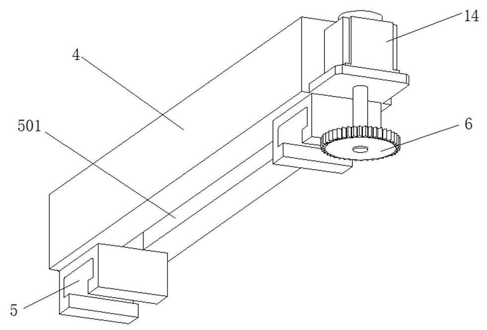
The invention relates to the technical field of mechanical devices, and particularly discloses a grabbing device for intelligent manufacturing of engineering equipment. The device comprises a transverse rail, an electric appliance cabinet and a grabbing mechanism, a moving beam is arranged above the transverse rail, a walking motor is installed at the rear end face of the moving beam, a power gear is connected to the lower end of an output shaft of the walking motor, a gear rack meshed with the power gear is connected to the outer side face of the transverse rail, and a lead screw motor is arranged on the front side face of the moving beam; a moving groove is formed in the lower surface of the moving beam, a lead screw is arranged in the moving groove, a moving block is arranged in the moving groove, a connecting column extending out of the moving groove is connected to the moving block, and the lower end of the connecting column is connected with the grabbing mechanism; and according to the grabbing device, accurate position adjustment and accurate grabbing of an object can be achieved, it is effectively guaranteed that slipping does not occur when the object is grabbed, damage to the object due to too large clamping force is prevented, and the use reliability of the grabbing device is effectively guaranteed.

Description

technical field [0001] The invention relates to the technical field of mechanical devices, and specifically discloses a grabbing device for intelligent manufacturing of engineering equipment. Background technique [0002] In the production line of intelligent manufacturing of engineering equipment, it is necessary to use the grabbing device to grab the parts of the equipment, and then move, place or assemble the grabbed parts. At present, in large-scale engineering equipment manufacturing plants, ABB robots and fixtures are used to grab parts and components, and the use effect is excellent. However, since ABB robots cost hundreds of thousands, for some small engineering equipment manufacturing Enterprises do not have enough funds to purchase ABB robots, so they need to carry them manually or design some simple grabbing devices for operation. [0003] For example, the utility model with the application number CN2020207835012 discloses a mechanically manufactured grasping dev...

Claims


Application Information

Patent Timeline
Patent Type & Authority Applications(China)
IPC IPC(8): B65G47/90B65G47/53
CPCB65G47/905B65G47/901B65G47/53
Inventor 姚雪
Owner 江苏极上建设有限公司
Learn More