Human body rotating table for examination in hospital radiology department
A technology of radiology and rotary table, which is applied in the field of medical equipment, can solve problems such as poor stability and inability to accurately adjust the patient's angle, and achieve the effects of reducing friction, improving inspection efficiency, and improving stability
- Summary
- Abstract
- Description
- Claims
- Application Information
AI Technical Summary
Problems solved by technology
Method used
Image
Examples
Embodiment 1
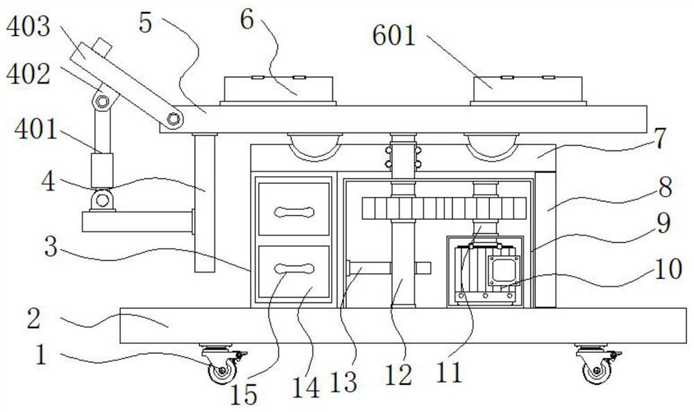
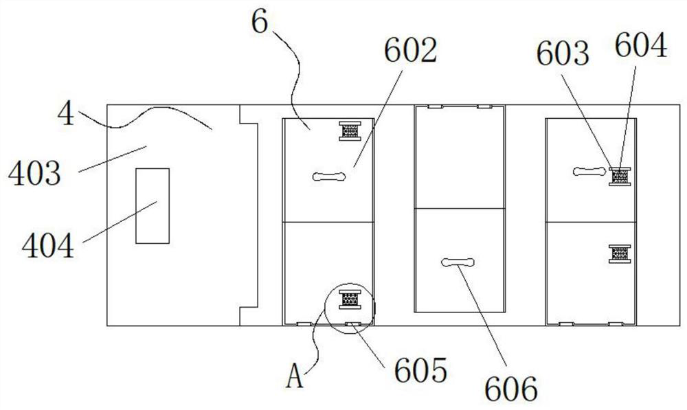
[0026] Example 1: See Figure 1-6 , a human body rotating table for hospital radiology inspection, comprising fixed casters 1 and a base plate 2, fixed casters 1 are respectively arranged at the four corners of the bottom end of the base plate 2, a protective shell 9 is fixedly connected to the top of the base plate 2, and the protective shell 9 The top is fixedly connected with a horizontal plate 7, the top of the horizontal plate 7 is provided with a main bed board 5, the top of the main bed board 5 is provided with a protective structure 6, one side of the top of the bottom board 2 is provided with a support rod 8, and the other side of the top of the bottom board 2 is fixed. Connected with a support frame 3, the bottom and top of the support frame 3 are provided with a drawer 14, one end of the drawer 14 is fixedly connected with a second handle 15, the other side of the main bed board 5 is provided with an adjustment mechanism 4, and the inside of the protective shell 9 E...
Embodiment 2
[0030] Embodiment 2: The bottom end of the other side inside the protective shell 9 is fixedly connected with the limit rod 13, the inside of the horizontal plate 7 is fixedly connected with a reserved groove 20, and both sides of the reserved groove 20 are fixedly connected with a rolling groove 21, and the rolling groove 21 is fixedly connected with the inside of the horizontal plate 7. The inside of the groove 21 is provided with balls 22, the two sides of the bottom end of the main bed board 5 are fixedly connected with the limit block 18, the top inside the horizontal plate 7 is fixedly connected with the limit groove 19, and the connecting shaft 12 is fixedly connected at the center of the bottom end of the main bed board 5 , the connecting shaft 12 runs through the inside of the reserved groove 20, the limit block 18 is embedded in the inside of the limit groove 19, and a sliding connection is formed between the limit block 18 and the limit groove 19;
[0031] Specifical...
Embodiment 3
[0032] Embodiment 3: The adjustment mechanism 4 is composed of an electric push rod 401, a mounting block 402, an auxiliary bed board 403, a headrest 404, a connecting rod 405 and a support plate 406. The connecting rod 405 is fixedly connected to the other side of the bottom end of the main bed board 5, and connected One side of the rod 405 is fixedly connected with a support plate 406, and the top of the support plate 406 is movably hinged with an electric push rod 401;
[0033] Specifically, such as figure 1 , figure 2 with Image 6 As shown, when it is necessary to adjust the inclination angle of the auxiliary bed board 403, start the electric push rod 401, and the electric push rod 401 will raise one side of the auxiliary bed board 403 through the hinge shaft and the installation block 402, and can be adjusted by raising one side of the auxiliary bed board 403 The inclination angle of the auxiliary bed board 403 enables the patient's back to be supported during the exa...
PUM
 Abstract
Description
Claims
Application Information
 - R&D
- Intellectual Property
- Life Sciences
- Materials
- Tech Scout
- Unparalleled Data Quality
- Higher Quality Content
- 60% Fewer Hallucinations
Browse by: Latest US Patents, China's latest patents, Technical Efficacy Thesaurus, Application Domain, Technology Topic, Popular Technical Reports.
© 2025 PatSnap. All rights reserved.Legal|Privacy policy|Modern Slavery Act Transparency Statement|Sitemap|About US| Contact US: help@patsnap.com


