Synchronous unfolding mechanism applied to liquid medicine spraying device

A technology of spraying device and deployment mechanism, applied in the application, catching or killing device of insects, animal husbandry, etc., can solve problems such as unfavorable spraying work, unable to adjust spraying mode, increase workload and time, etc., to save Time, money, and labor-intensive effects of setting up a full-scale irrigation system

Active Publication Date: 2021-08-31
GUANGDONG NENGDA HIGHER LEVEL HIGHWAY MAINTENANCE CO LTD
View PDF6 Cites 0 Cited by
  • Summary
  • Abstract
  • Description
  • Claims
  • Application Information

AI Technical Summary

Problems solved by technology

In the high-speed traffic flow, the traditional operation mode has great potential safety hazards, which is not conducive to the development of spraying work
[0004] The traditional operation method has the following shortcomings. The manual hand-held spraying method greatly increases the labor force and reduces the work efficiency. At the same time, there are safety hazards in the operation process; and the spraying method is single, and the spraying mode cannot be adjusted according to the actual situation. , because the existing spraying method only sprays one side of the central isolation green belt, it needs to go back and forth to complete the comprehensive irrigation or insecticide, which greatly increases the workload and time. Due to the large structure of the comprehensive irrigation, For this reason, it is necessary to provide a space-saving device capable of spraying and irrigating the central isolation green belt in all directions; it is also necessary to provide a structure in which the swing rods on both sides swing symmetrically

Method used


Image

  • Synchronous unfolding mechanism applied to liquid medicine spraying device
  • Synchronous unfolding mechanism applied to liquid medicine spraying device
  • Synchronous unfolding mechanism applied to liquid medicine spraying device

Examples


Embodiment Construction

[0033] The following will clearly and completely describe the technical solutions in the embodiments of the present invention with reference to the accompanying drawings in the embodiments of the present invention. Obviously, the described embodiments are only some, not all, embodiments of the present invention. Based on the embodiments of the present invention, all other embodiments obtained by persons of ordinary skill in the art without making creative efforts belong to the protection scope of the present invention.

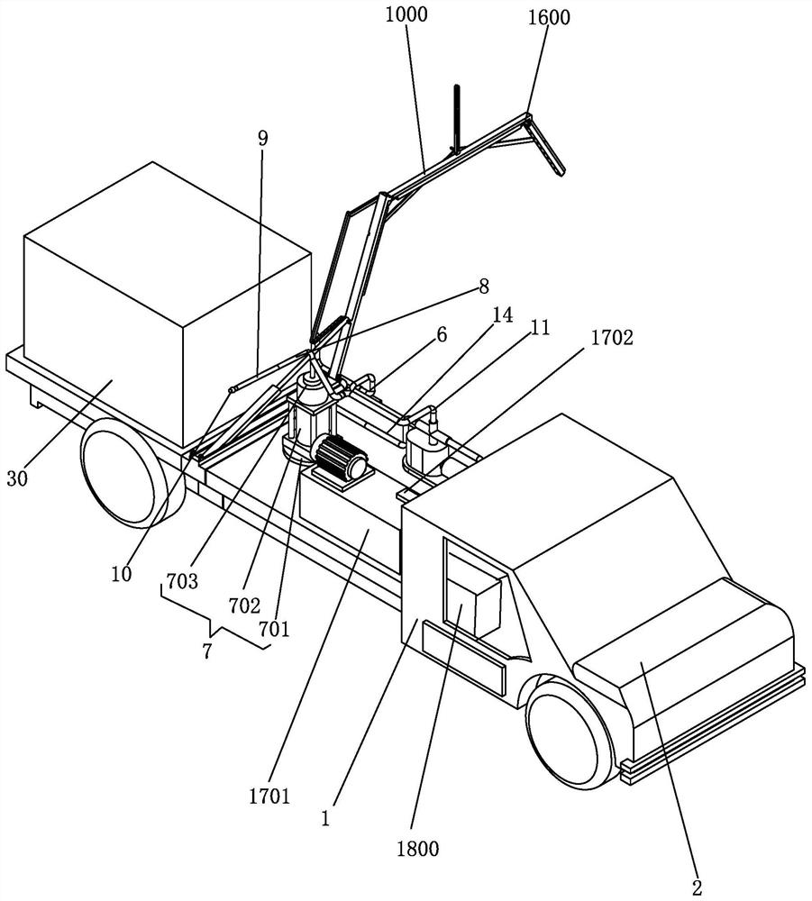
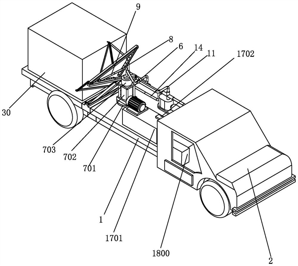
[0034] see Figure 1-16 , the present invention provides

[0035] A synchronous deployment mechanism applied to a liquid medicine spraying device, comprising a car body 1, a control room 2 and a water tank 30 are arranged on the car body 1, and a hydraulic power unit 3 is arranged on the car body 1 to provide power for liquid ejection , the hydraulic power station 3 is provided with a water outlet 4 and a water inlet 5, and an input pipeline 6 is connected be...


PUM


Abstract

The invention discloses a synchronous unfolding mechanism applied to a liquid medicine spraying device. The synchronous unfolding mechanism comprises a second swing rod, a middle rod is arranged on the second swing rod, a sliding groove is formed in the middle rod, a sliding block is movably arranged in the sliding groove, a synchronous shaft is arranged on the sliding block, a first swing rod is hinged to one end of the second swing rod, and a third swing rod is hinged to the other end of the second swing rod. A first synchronous shaft hole is formed in the first swing rod, a second synchronous shaft hole is formed in the third swing rod, a first synchronous connecting rod is hinged between the synchronous shaft and the first synchronous shaft hole, and a second synchronous connecting rod is hinged between the synchronous shaft and the second synchronous shaft hole. Meanwhile, the invention provides irrigation equipment capable of automatically folding and automatically erecting a comprehensive spraying mechanism. The space and the time for erecting the comprehensive irrigation mechanism are greatly saved, the structure is simple, and use is convenient; and meanwhile, the swing rods on the two sides are symmetrically and synchronously unfolded or closed at the same angle, and it is guaranteed that the two sides of central greening are evenly irrigated.

Description

[0001] This application is a divisional application, the application number of the original application is 2020112602197, the application date is November 12, 2020, and the title of the invention is "an electronically controlled multi-functional liquid medicine spraying device". technical field [0002] The invention relates to expressway greening maintenance operation equipment, in particular to a synchronous deployment mechanism applied to a liquid medicine spraying device. Background technique [0003] In the existing highway greening and maintenance operation design, in addition to the basic mechanized pruning, there are also tasks such as sprinkling plants to prevent drought, spraying pesticides to kill insects, spraying pesticides and weeds during the greening management of the central isolation green belt and roadside slopes. In the high-speed traffic flow, the traditional operation mode has great potential safety hazards, which is not conducive to the development of s...

Claims


Application Information

Patent Timeline
Patent Type & Authority Applications(China)
IPC IPC(8): A01M7/00
CPCA01M7/0042
Inventor 陈链冰林利聪罗中佳黄伟李志明李善法吴开陈达隆彭霞刘智科
Owner GUANGDONG NENGDA HIGHER LEVEL HIGHWAY MAINTENANCE CO LTD
Why Eureka
Try Eureka