Wind vane for generator based on dry-wet separation

A dry-wet separation and generator technology, which is applied to wind turbines, engines, and wind power generation that store gravitational potential energy, can solve problems such as controlling the operating power of generators, excessive damage to generators, and achieve faster incineration and avoid flames. fire effect

Pending Publication Date: 2021-08-24
朱荣飞
View PDF9 Cites 2 Cited by
  • Summary
  • Abstract
  • Description
  • Claims
  • Application Information

AI Technical Summary

Problems solved by technology

[0002] According to the research results, the volume ratio of air volume to hydrogen is about 5:2, which can produce an explosion. The most violent explosion is hydrogen and oxygen. When the volume ratio is 2:1, an explosion will occur. The existing wind vane for generators, in In the process of garbage incineration, the operating power of the generator cannot be controlled by judging the wind direction, which may easily lead to excessive operation of the generator and cause damage, and it is also impossible to electrolyze water through the generator to produce hydrogen and oxygen to support the combustion of garbage incineration, so , it is necessary to design a wind vane for generators based on dry-wet separation that can automatically change the engine power and adjust the degree of combustion

Method used


Image

  • Wind vane for generator based on dry-wet separation
  • Wind vane for generator based on dry-wet separation
  • Wind vane for generator based on dry-wet separation

Examples


Embodiment Construction

[0021] The following will clearly and completely describe the technical solutions in the embodiments of the present invention with reference to the accompanying drawings in the embodiments of the present invention. Obviously, the described embodiments are only some, not all, embodiments of the present invention. Based on the embodiments of the present invention, all other embodiments obtained by persons of ordinary skill in the art without making creative efforts belong to the protection scope of the present invention.

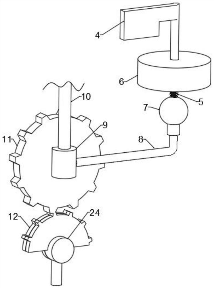
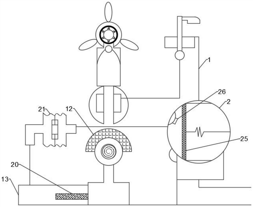
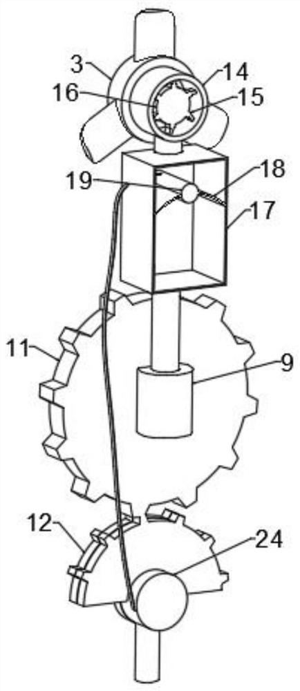
[0022] see Figure 1-4 , the present invention provides a technical solution: a wind vane for a generator based on dry-wet separation, including a housing 1, an incinerator 2 is fixed inside the housing 1, a generator is fixed at the middle bottom of the housing 1, and a gear is connected to the upper part of the generator. Fan 3, the right side of the fan 3 is provided with a wind vane 4, the wind vane 4 is threadedly connected to the top of the housing 1, th...


PUM


Abstract

The invention discloses a wind vane for a generator based on dry-wet separation, the wind vane comprises a shell, an incinerator is fixed in the shell, the generator is fixed at the bottom of the middle of the shell, a fan is in gear connection with the upper part of the generator, the wind vane is arranged on the right side of the fan, and the wind vane is in threaded connection with the upper part of the shell. An electrolysis box is fixed to the left side of the generator, the right side of the incinerator is connected with an air opening through a pipeline, the middle bearing of the weather vane is connected with a threaded rod, the bottom end of the threaded rod is in threaded connection with a nut, the nut is fixedly connected with the inner wall of the upper end of the shell, a ball is fixed to the bottom end of the threaded rod, and a fixing rod is connected to the lower portion of the ball through a bearing. A sleeve is fixed to the left end of the fixing rod, a sliding rod is connected to the middle of the sleeve in a sleeving mode, the sliding rod is fixedly connected with the inner wall of the shell, and a gear disc is connected to the front side of the sleeve through a bearing. The wind vane can automatically change the engine power and adjust the combustion support degree.

Description

technical field [0001] The invention relates to the technical field of dry-wet separation, in particular to a wind vane for generators based on dry-wet separation. Background technique [0002] According to the research results, the volume ratio of air volume to hydrogen is about 5:2, which can produce an explosion. The most violent explosion is hydrogen and oxygen. When the volume ratio is 2:1, an explosion will occur. The existing wind vane for generators, in In the process of garbage incineration, the operating power of the generator cannot be controlled by judging the wind direction, which may easily lead to excessive operation of the generator and cause damage, and it is also impossible to electrolyze water through the generator to produce hydrogen and oxygen to support the combustion of garbage incineration, so Therefore, it is necessary to design a wind vane for generators based on dry-wet separation that can automatically change the engine power and adjust the degree...

Claims


Application Information

Patent Timeline
Patent Type & Authority Applications(China)
IPC IPC(8): C25B9/17C25B9/65C25B1/04G01P13/02F03D9/19F03D15/00F23G5/12
CPCG01P13/02F03D9/19F03D15/00F23G5/12Y02E60/36Y02E70/30Y02E10/72
Inventor 朱荣飞
Owner 朱荣飞
Why Eureka
Try Eureka