Endoscope cutting anastomat with nail anvil capable of moving up and down and rotating
A stapler and anvil technology, applied in the field of staplers, can solve the problems of affecting the quality of pulling, high cost of use, and inconvenient work, and achieve the effects of reducing mishandling of adjustment knobs, reducing work intensity, and improving work accuracy
- Summary
- Abstract
- Description
- Claims
- Application Information
AI Technical Summary
Problems solved by technology
Method used
Image
Examples
Embodiment 1
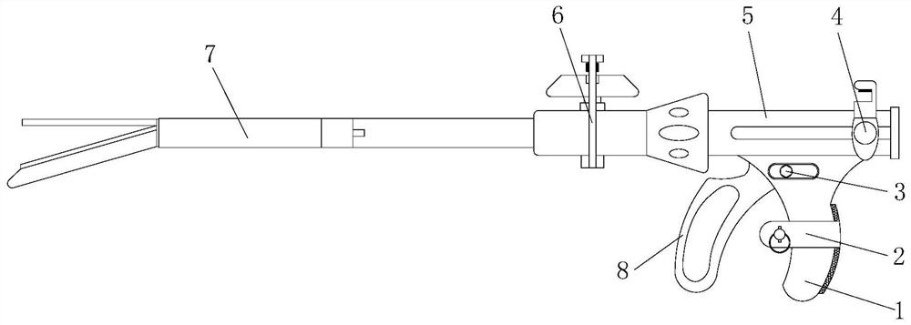
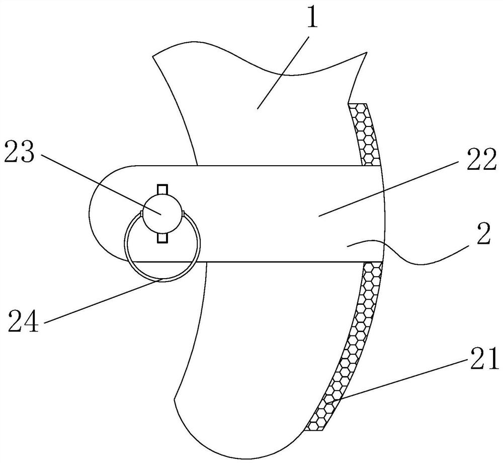
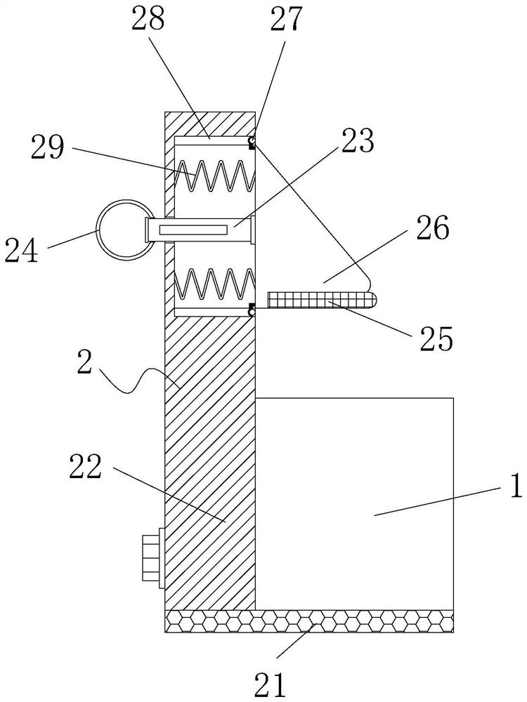
[0029] see Figure 1-6 , the present invention provides the following technical solutions: a laparoscopic cutting anastomat that anvil can move up and down and rotate, including holding handle 1, the upper end of holding handle 1 is provided with safety button 3, and the upper end of safety button 3 is provided with installation The housing 5 is provided with a nail cartridge assembly 7 on the side where the housing 5 is installed, and a firing handle 8 is provided on the side holding the handle 1. The position locking assembly 2 comprises a mounting frame 22, a connecting rod 23, a limit block 26, a blocking block 27, a guide groove 28 and a limit spring 29, wherein the surface side of the holding handle 1 is provided with a mounting frame 22, and the mounting frame 22 is installed The inside of the frame 22 is symmetrically provided with a guide groove 28, the inside of the guide groove 28 is provided with a blocking block 27, and a limit block 26 is arranged between the gui...
Embodiment 2
[0036] The difference between this embodiment and Embodiment 1 is that: specifically, a clamping and fixing assembly 6 is provided between the installation housing 5 and the staple cartridge assembly 7, and the clamping and fixing assembly 6 includes a fixing rod 61 and a limit slide 62 , installation slider 63, damping rotating shaft 64, rotating rod 65, limit plug 66, adjustment knob 67, adjustment housing 68 and connecting frame 69, wherein, one side of installation housing 5 is provided with adjustment housing 68, adjusts The bottom end of the housing 68 is provided with a connecting frame 69, and the upper end of one side of the connecting frame 69 is provided with a fixed rod 61, and the inside of the fixed rod 61 is provided with a limit chute 62, and the inside of the limit chute 62 is provided with a mounting slider 63. The inside of the installation slider 63 is provided with a damping shaft 64, one side of the damping shaft 64 is provided with a rotating rod 65, the ...
Embodiment 3
[0044] This embodiment differs from Embodiment 1 and Embodiment 2 in that: Specifically, the surface of the installation housing 5 is provided with a convenient adjustment assembly 4, and the convenient adjustment assembly 4 includes a push block 42, a connecting block 43 and a finger groove 44, Wherein, push blocks 42 are arranged symmetrically on both sides of the installation housing 5 , connecting blocks 43 are arranged on the upper ends of the pushing blocks 42 , and finger slots 44 are evenly spaced inside the connecting blocks 43 .
[0045] By adopting the above-mentioned technical scheme, when the pushing block 42 needs to be pulled to move, the finger is inserted into the finger groove 44, and the connecting block 43 is pulled to drive the pushing block 42 to move along the installation housing 5, ensuring that the pushing block 42 is pulled Convenience and stability, improve work efficiency and save human resources.
[0046] Specifically, the inner surface of the fin...
PUM
 Abstract
Description
Claims
Application Information
 - R&D
- Intellectual Property
- Life Sciences
- Materials
- Tech Scout
- Unparalleled Data Quality
- Higher Quality Content
- 60% Fewer Hallucinations
Browse by: Latest US Patents, China's latest patents, Technical Efficacy Thesaurus, Application Domain, Technology Topic, Popular Technical Reports.
© 2025 PatSnap. All rights reserved.Legal|Privacy policy|Modern Slavery Act Transparency Statement|Sitemap|About US| Contact US: help@patsnap.com


