Optical system, lens module and electronic equipment
An optical system and lens technology, applied in optics, optical components, instruments, etc., can solve the problem of not being able to meet a large field of view and high imaging quality at the same time
- Summary
- Abstract
- Description
- Claims
- Application Information
AI Technical Summary
Problems solved by technology
Method used
Image

Examples
no. 1 example
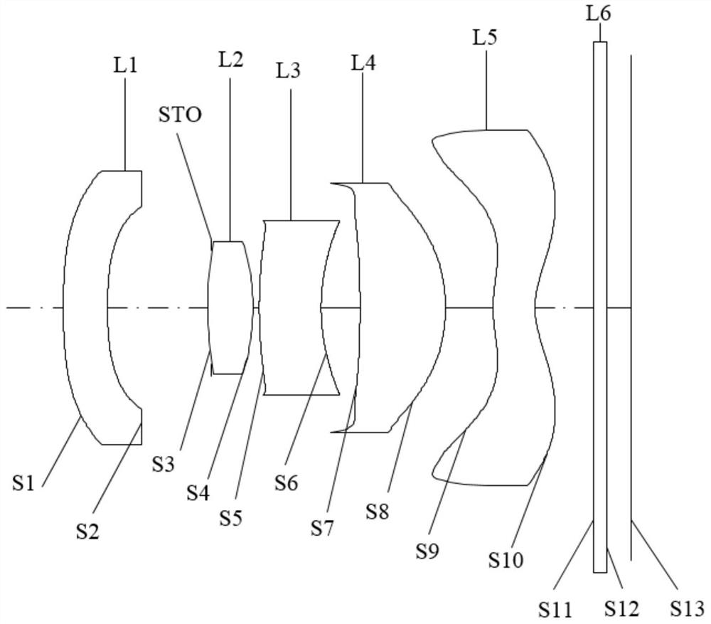
[0043] Please refer to Figure 1a and Figure 1b , the optical system of this embodiment includes in sequence from the object side to the image side along the optical axis direction:
[0044] The first lens L1 has a negative refracting force, the object side S1 of the first lens L1 is convex at the near optical axis, the image side S2 is concave at the near optical axis; the object side S1 of the first lens L1 is convex at the circumference , as the side S2 is concave at the circumference.
[0045] The second lens L2 has a positive refracting power. The object side S3 of the second lens L2 is convex at the near optical axis, and the image side S4 is convex at the near optical axis; the object side S3 of the second lens L2 is convex at the circumference. , like the side S4 is convex at the circumference.
[0046]The third lens L3 has a negative refracting power, the object side S5 of the third lens L3 is convex at the near optical axis, the image side S6 is concave at the nea...
no. 2 example
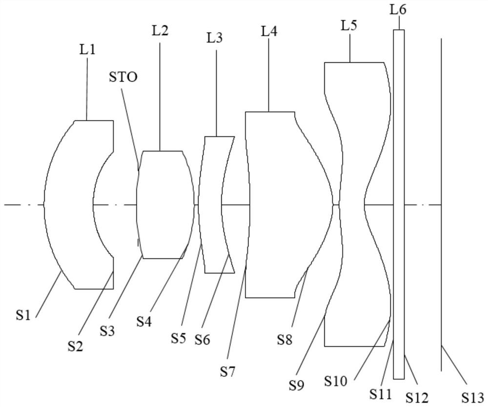
[0061] Please refer to Figure 2a and Figure 2b , the optical system of this embodiment includes in sequence from the object side to the image side along the optical axis direction:
[0062] The first lens L1 has a negative refracting force, the object side S1 of the first lens L1 is convex at the near optical axis, the image side S2 is concave at the near optical axis; the object side S1 of the first lens L1 is convex at the circumference , as the side S2 is concave at the circumference.
[0063] The second lens L2 has a positive refracting power. The object side S3 of the second lens L2 is convex at the near optical axis, and the image side S4 is convex at the near optical axis; the object side S3 of the second lens L2 is convex at the circumference. , like the side S4 is convex at the circumference.
[0064] The third lens L3 has a negative refracting power, the object side S5 of the third lens L3 is convex at the near optical axis, the image side S6 is concave at the n...
no. 3 example
[0078] Please refer to Figure 3a and Figure 3b , the optical system of this embodiment includes in sequence from the object side to the image side along the optical axis direction:
[0079] The first lens L1 has a negative refracting force, the object side S1 of the first lens L1 is convex at the near optical axis, the image side S2 is concave at the near optical axis; the object side S1 of the first lens L1 is convex at the circumference , as the side S2 is concave at the circumference.
[0080] The second lens L2 has a positive refracting power. The object side S3 of the second lens L2 is convex at the near optical axis, and the image side S4 is convex at the near optical axis; the object side S3 of the second lens L2 is convex at the circumference. , like the side S4 is convex at the circumference.
[0081] The third lens L3 has a negative refracting force, the object side S1 of the third lens L3 is convex at the near optical axis, the image side S2 is concave at the n...
PUM
 Abstract
Description
Claims
Application Information
 - Generate Ideas
- Intellectual Property
- Life Sciences
- Materials
- Tech Scout
- Unparalleled Data Quality
- Higher Quality Content
- 60% Fewer Hallucinations
Browse by: Latest US Patents, China's latest patents, Technical Efficacy Thesaurus, Application Domain, Technology Topic, Popular Technical Reports.
© 2025 PatSnap. All rights reserved.Legal|Privacy policy|Modern Slavery Act Transparency Statement|Sitemap|About US| Contact US: help@patsnap.com