
Intelligent hot melting sprue device for injection mold

A technology for injection molds and molds, which is applied in the field of intelligent hot-melt gate devices for injection molds. It can solve the problems of destroying the toughness of injection molded parts and the inconsistency of the melting state of injection molding raw materials, so as to ensure long-term use, avoid solid residues, and improve processing quality. Guaranteed effect

Pending Publication Date: 2021-08-20
徐剑
View PDF1 Cites 0 Cited by
  • Summary
  • Abstract
  • Description
  • Claims
  • Application Information

AI Technical Summary

Problems solved by technology

[0006] Aiming at the deficiencies of the prior art, the present invention provides an intelligent hot-melt gate device for injection molds, which solves the problem of solid residues in the molten liquid of injection molding raw materials during the use of the existing intelligent hot-melt gate devices for injection molds. Inconsistencies in the molten state of injection molding raw materials, and solid particles will also destroy the stress point of the injection molded part and the toughness of the surrounding area

Method used


Image

  • Intelligent hot melting sprue device for injection mold
  • Intelligent hot melting sprue device for injection mold
  • Intelligent hot melting sprue device for injection mold

Examples


Embodiment 1

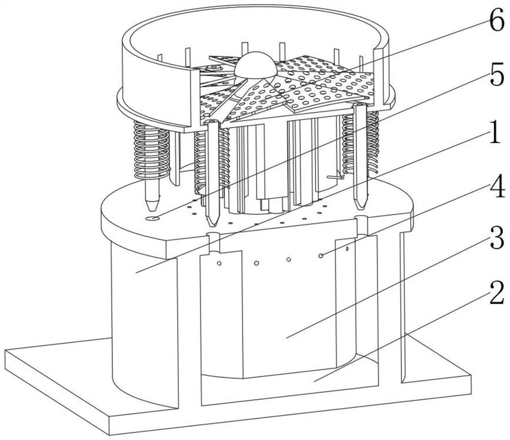
[0039] see Figure 1-2 , the present invention provides a technical solution: an intelligent hot-melt gate device for injection molds, specifically comprising:

[0040] Bottom mold 1, the bottom mold 1 has a barrel mold, and a mold seat plate 2 fixed on the bottom of the barrel mold, and a top mold 3 arranged in the inner cavity of the barrel mold, and capillary holes provided on the outer surface of the top mold 3 4, and the injection gate 5 located on the outside of the capillary hole 4 on the top mold 3, and the gate mechanism 6 installed in the middle of the top of the top mold 3, through the L-shaped pipeline design of the capillary hole 4 itself, it is convenient for the gas to flow in the horizontal layer Rapid flow on the upper surface is convenient to discharge the internal gas and avoid the phenomenon of air bubbles in the injection mold due to the residual gas. At the same time, the vertical design of the capillary hole 4 and the injection molded part is convenient to...

Embodiment 2

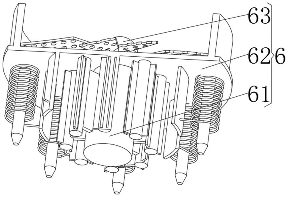
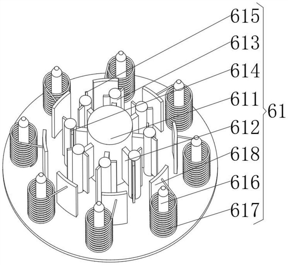
[0045] see Figure 1-3 , On the basis of Embodiment 1, the present invention provides a technical solution: the hot-melt mechanism 61 includes:

[0046] A rotator 611, the rotator 611 has a columnar body, a mounting plate 612 fixed on the outer surface of the columnar body, a magnetic column 613 fixed on the other side of the mounting plate 612, and a through slot 614 in the middle of the magnetic column 613 , and the offset wind deflector 615 arranged in the inner cavity of the through groove 614; the position of the magnetic field is changed by the rotation of the magnetic column 613 component, and the component is powered by the magnetoelectric effect, which saves energy and reduces energy consumption At the same time, the inclination design of the offset wind deflector 615 allows the airflow to diffuse outwards, dissipates air to some components, and ensures the long-term use of the components.

[0047] Injection sprue tube 616, the injection sprue tube 616 has a cylinder...

Embodiment 3

[0051] see Figure 1-4 , on the basis of Embodiment 1 and Embodiment 2, the present invention provides a technical solution: the injection gate tube 616 includes:

[0052] A cylinder column A1, the cylinder column A1 has an angular column cylinder, and a staggered fan plate A2 arranged on the inner surface of the angular column cylinder, and an axis column A3 installed in the center of the staggered fan plate A2;

[0053] A driver A4, the driver A4 has a motor body and a fixed wheel A5 fixed on the top of the column A1, and the motor body passes through the column A1 and extends to the inner cavity of the column A1. Through the rotation of the staggered fan plate A2, the injection molding melt flows slowly, avoiding the rapid flow of the injection molding melt and causing bubbles inside, and at the same time diverting the injection molding melt so that it flows along the inner wall, better for the interior The airflow is pressurized and discharged, while better shaping.

[0...


PUM


Abstract

The invention discloses an intelligent hot melting sprue device for an injection mold. The intelligent hot melting sprue device specifically comprises a bottom mold. The bottom mold is provided with a cylinder-shaped mold, a capillary hole formed in the outer surface of a top mold, an injection sprue formed in the portion, located on the outer side of the capillary hole, of the top mold, and a sprue mechanism installed at the middle position of the top of the top mold. The sprue mechanism comprises a hot melting mechanism. The hot melting mechanism comprises a flow guide main body, a partition round plate installed on the top of the flow guide main body, and an auxiliary mechanism installed on the top of the partition round plate. The invention relates to the technical field of injection molds. By means of design of the hot melting mechanism, secondary hot melting is carried out on a raw material of an injected part, solid residues existing in molten liquid of the injection raw material are avoided, consistency of the molten state of the injection raw material is ensured, the machining quality is ensured, meanwhile, solid particles cause damage to a stress point and the peripheral toughness of the injected part, and the hot melting mechanism can protect the strength and the toughness of the injected part.

Description

technical field [0001] The invention relates to the technical field of injection molds, in particular to an intelligent hot-melt gate device for injection molds. Background technique [0002] The gate is the part that connects the runner and the molding cavity in the injection mold. The function of the gate is to make the molten plastic from the runner enter and fill the molding cavity at the fastest speed. When the molding cavity is full, the gate can be quickly cooled and closed to prevent the uncooled plastic in the molding cavity from flowing back. The structure and position selection of the gate will directly affect whether the molten material can be intact and high-quality injection molding. [0003] According to the Chinese patent CN111730818A, a four-stage structure of a primary runner, a restricted gate, a secondary runner and an unrestricted gate is designed; the plastic melt is accelerated and rubbed through a restricted gate whose inlet is larger than the outlet...

Claims


Application Information

Patent Timeline
IPC IPC(8): B29C45/26B29C45/27B29C45/43B29C45/73B29C45/17B29B13/02B29B13/10B29B7/16
CPCB29B7/16B29B13/022B29B13/10B29C45/1753B29C45/2602B29C45/2708B29C45/2737B29C45/43B29C45/73B29C2045/2709B29C2045/2743
Inventor 徐剑
Owner 徐剑
Learn More