


Quick Research
Generate reliable direction feasibility study reports for your R&D in just a few steps.

Technical Q&A
Discover and master advanced knowledge NOW. Basics, ideas, possibilities, all at once.

Find Solutions
As an expert in R&D theories, this can generate solutions to your technical problems instantly.

Evaluate Feasibility
Analyze your overall solution with one click, know your potential R&D risks in advance.

Monitor Landscape
Get weekly tech updates, stay abreast of the latest tech innovations and key insights.
Mechanical slip tubing anchor
A slip oil pipe and mechanical technology, which is applied in the field of oil pipe fixing equipment, can solve the problems of the anchors being difficult to disassemble and the effect of folding is limited, and achieves the effect of ensuring easy disassembly characteristics and improving the degree of installation and tightening.
- Summary
- Abstract
- Description
- Claims
- Application Information
AI Technical Summary
Problems solved by technology
Method used
Image


Examples
Embodiment 1
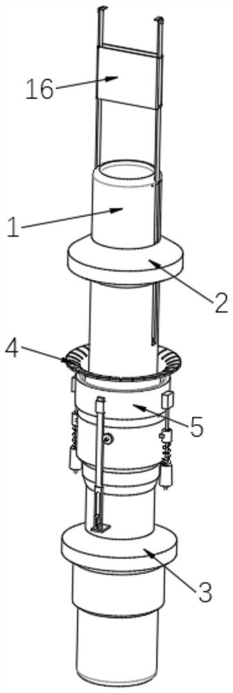
[0032] refer to Figure 1-8 As shown, a mechanical slip oil pipe anchor includes a central pipe 1 and an upper joint 2 and a lower joint 3 which are sequentially sleeved outside the central pipe 1, and slips are sleeved and installed between the upper joint 2 and the lower joint 3 4. The outer sleeve of the slip sheet 4 is equipped with a matching finishing mechanism, and the top of the central tube 1 is equipped with a locking mechanism matching the upper joint 2 .
[0033] The finishing mechanism includes a transmission box 15 fixed on the front side of the central tube 1 through a connecting block 21. The top of the slip sheet 4 is provided with a pressing ring 5, and the middle outer wall of the slip sheet 4 is symmetrically installed with a pressing ring 5. The pad 26 set against the lower end surface of the ring 5, a rack bar 12 is slidably inserted in the transmission box 15, and the top of the rack bar 12 is provided with a limit frame 11 fixed on the outer wall of the...
Embodiment 2
[0036] On the basis of Embodiment 1, two fixed sleeves 8 are symmetrically fixed to the left and right sides of the rack bar 12 on the outer wall of the slip sheet 4, and columns 7 are slidably inserted in the two fixed sleeves 8, and the tops of the two columns 7 Both are fixed by the fixing block 6 and the outer wall of the pressing ring 5, and the bottoms of the two columns 7 are fixedly equipped with anti-off columns 10, and the two columns 7 are equipped with springs 9, and the ends of the two springs 9 The two ends are set against the fixed sleeve 8 and the anti-falling cylinder 10 at the first and last ends of the two columns 7 respectively.
[0037] In this embodiment: through the elastic return ability of the column 7, the fixed sleeve 8, and the spring 9, the up and down stable movement of the pressing ring 5 driven by the rack bar 12 is realized, and the regularity of the pressing ring 5 when it moves vertically is improved. .
[0038] working principle:
PUM
 Abstract
Description
Claims
Application Information
 - R&D Engineer
- R&D Manager
- IP Professional
- Industry Leading Data Capabilities
- Powerful AI technology
- Patent DNA Extraction
Browse by: Latest US Patents, China's latest patents, Technical Efficacy Thesaurus, Application Domain, Technology Topic, Popular Technical Reports.
© 2024 PatSnap. All rights reserved.Legal|Privacy policy|Modern Slavery Act Transparency Statement|Sitemap|About US| Contact US: help@patsnap.com