
A laser profile sensor eye-in-hand calibration method based on a ladder-shaped calibration object

A calibration object and step-shaped technology, applied in the field of robot three-dimensional vision, can solve the problems of low precision and cumbersome calibration process, and achieve the effect of easy operation and strong industrial application potential.

Active Publication Date: 2022-04-01
HUNAN UNIV
View PDF10 Cites 0 Cited by
  • Summary
  • Abstract
  • Description
  • Claims
  • Application Information

AI Technical Summary

Problems solved by technology

[0010] The purpose of the present invention is to solve the problems of low accuracy and cumbersome calibration process of the existing laser profile sensor calibration algorithm, and to provide an effective, scientific and reasonable laser profile sensor calibration object and an improved calibration algorithm

Method used


Image

  • A laser profile sensor eye-in-hand calibration method based on a ladder-shaped calibration object
  • A laser profile sensor eye-in-hand calibration method based on a ladder-shaped calibration object
  • A laser profile sensor eye-in-hand calibration method based on a ladder-shaped calibration object

Examples


Embodiment Construction

[0062] Next, the present invention will be described in detail with reference to the drawings and specific embodiments. This embodiment is based on the premise of the technical solution of the present invention, giving detailed implementation and specific calibration process, but the embodiment of the present invention is not limited to the present invention.

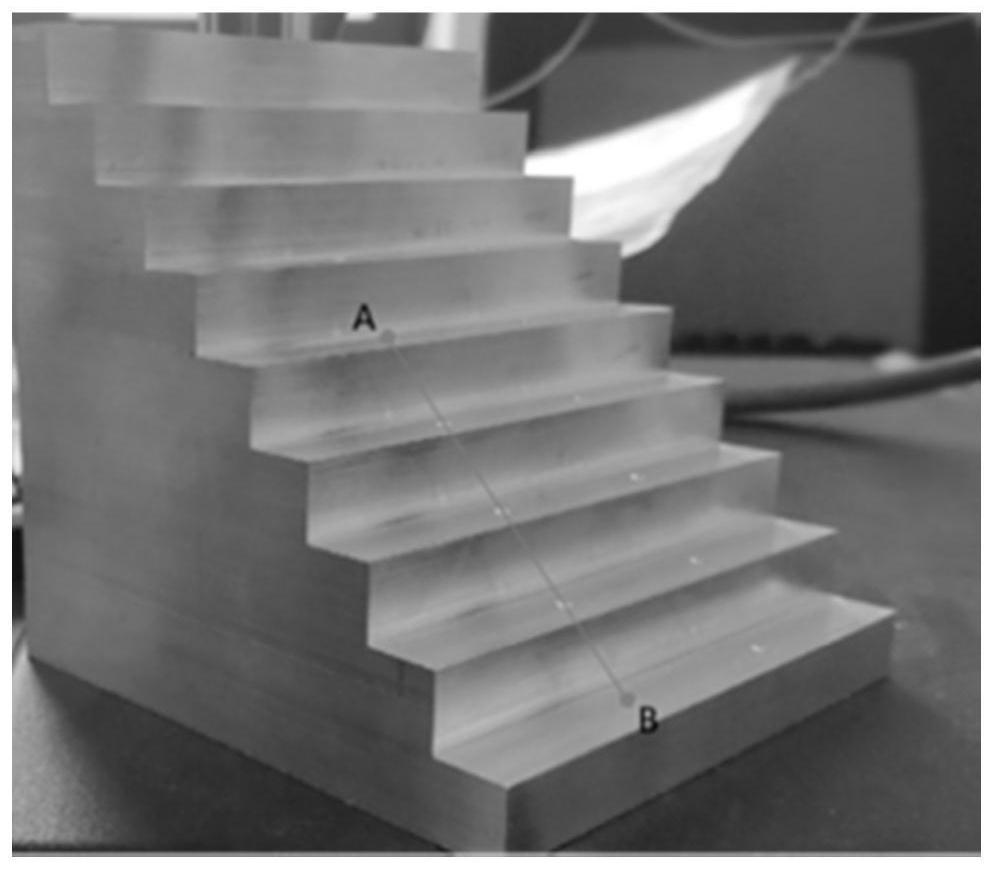
[0063] The present invention proposes a laser profile sensor calibration method based on a stepped calibration object, which is characterized in that it comprises the following steps:

[0064] S1. Calibrate the tool coordinate system of the robot. The ladder-shaped calibration object is placed on the workbench processed by the robot, and the robot is used to calibrate the user coordinate system with the ladder-shaped calibration object;

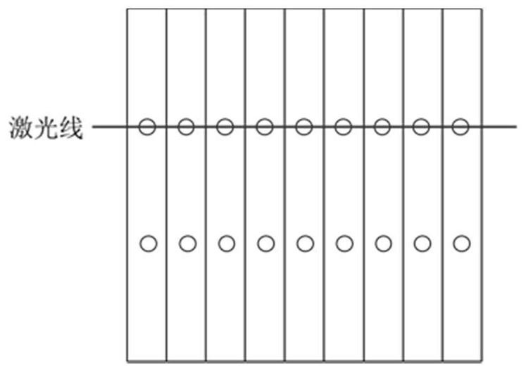
[0065] S2. Control the robot to align the line laser of the laser profile sensor with each marking point on the stepped calibration object, scan the stepped calibration object at this ...


PUM


Abstract

The present invention proposes a step-type calibration object and a hand-eye calibration method (eye-in-hand mode) of a laser profile sensor based on the step-type calibration object, and relates to the hand-eye calibration technology of the laser profile sensor. The ladder-shaped calibration object used in the present invention has obvious characteristics, and these features are easy to be detected and extracted by the sensor. Each calibration only needs to align the marking points on the ladder-shaped calibration object, extract the corner points of each step and use the RANSAC method for these corner points Fit a straight line, use the straight line to correct the feature point data scanned by the laser profile sensor, and then construct the hand-eye equation according to the coordinates of these points in the robot base coordinate system, and use these data to solve the hand-eye matrix equation. High-precision calibration results can be obtained with one scan.

Description

technical field [0001] The invention relates to the field of three-dimensional vision of robots, in particular to an eye-in-hand calibration method for a laser profile sensor based on a ladder-shaped calibration object. Background technique [0002] In robotics and mathematics, the hand-eye calibration problem is the problem of determining the transformation between a robot's end effector and a camera, or between a robot's base and a world coordinate system. In actual use scenarios, the hand-eye calibration problem is often solved, where the matrix represents the characteristics of the robot's base coordinate system, the matrix represents the characteristics of the visual sensor coordinate system, and and are unknown transformation matrices. When the special case occurs in , the equation for solving the hand-eye calibration becomes, which is also the most common case for solving the equation for the hand-eye calibration. For example, in the use scenario of two-dimensional g...

Claims


Application Information

Patent Timeline
Patent Type & Authority Patents(China)
IPC IPC(8): G01B11/24
CPCG01B11/24
Inventor 孙炜苑河南刘乃铭刘权利舒帅
Owner HUNAN UNIV
Learn More