An urban underground drainage pump with sewage interception function
An underground drainage and urban technology, which is applied to components, pumps, and pump components of elastic fluid pumping devices, can solve problems such as poor heat dissipation, blockage of the pump body, and damage to components, so as to improve heat dissipation efficiency and avoid Clogging and damage, the effect of preventing clogging
- Summary
- Abstract
- Description
- Claims
- Application Information
AI Technical Summary
Problems solved by technology
Method used
Image
Examples
Embodiment 1
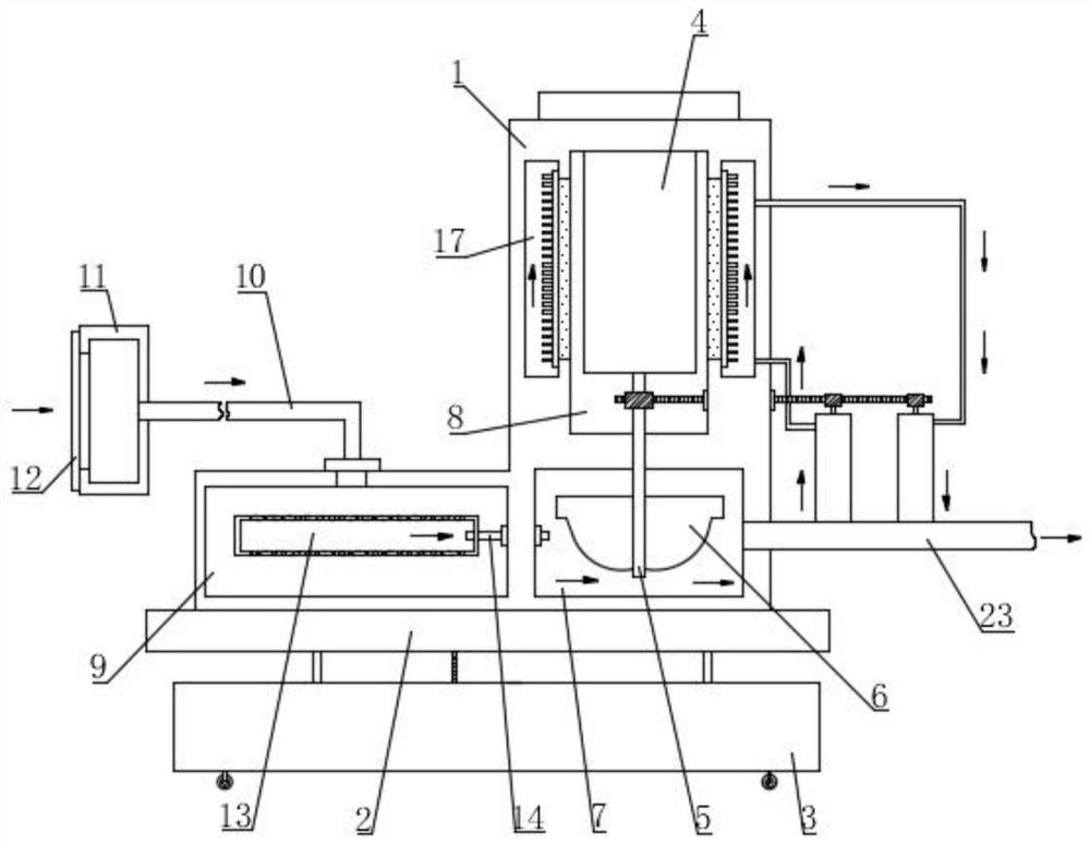
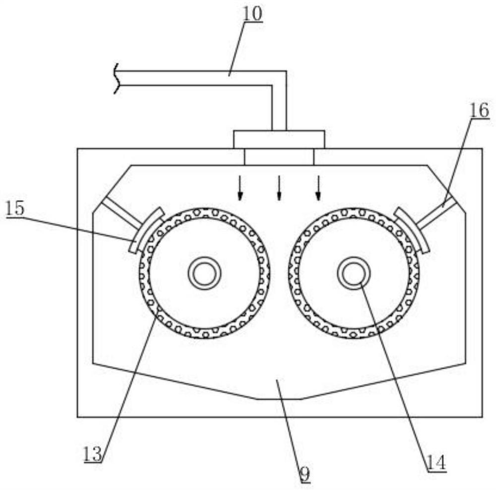
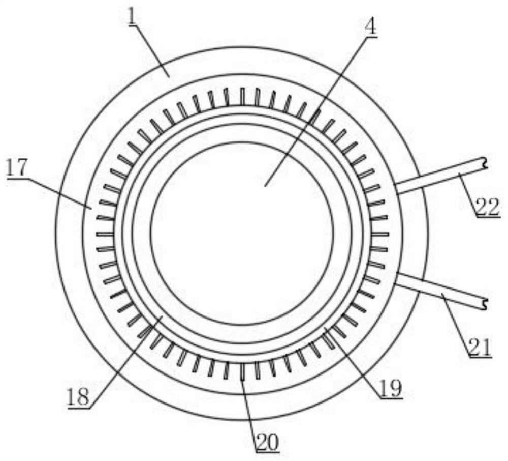
[0047] like Figure 1-6 As shown, the present invention proposes an urban underground drainage pump with a sewage interception function, which includes a pump body 1, a bearing seat 2, a fixed seat 3, a driving mechanism 4, a rotating shaft 5, an impeller 6, a water inlet chamber 7, and a Chamber 8, suction pipe 10 and drain pipe 23, the pump body 1 is fixed on the top of the bearing seat 2 by bolts, the pump body 1 is provided with a placement chamber 8 and a water inlet chamber 7, and the placement chamber 8 is located above the water inlet chamber 7 , the driving mechanism 4 is fixedly installed in the placement chamber 8 by bolts, the rotating shaft 5 is vertically arranged and connected in rotation with the pump body 1, the output end of the driving mechanism 4 is connected with the rotating shaft 5, and the driving mechanism 4 makes the rotating shaft 5 rotate, The impeller 6 is fixedly installed on the rotating shaft 5 by bolts and is located in the water inlet chamber ...
Embodiment 2
[0051] like Figure 7-11As shown, this embodiment is basically the same as Embodiment 1. Preferably, the bearing seat 2 is located above the fixed seat 3, and an anti-seismic assembly 32 is installed between the bearing seat 2 and the fixed seat 3, and the anti-seismic assembly 32 includes a first rack 3201, transmission rod 3202, first gear 3203, winding rod 3204, first bevel gear 3205, second bevel gear 3206, first limiting cavity 3207, movable magnet 3208, connecting rope 3209, guide rod 3210, first spring 3211, a fixed magnet 3212 and a rope wheel 3213; the inside of the fixed seat 3 is provided with a cavity 33, and the winding rod 3204 is vertically arranged in the cavity 33 and is connected to the fixed seat 3 through a bearing. The winding rod 3204 can Rotate in the cavity 33, the transmission rod 3202 is installed by bearing rotation in the cavity 33, the first bevel gear 3205 is arranged on the transmission rod 3202, the transmission rod 3202 drives the first bevel g...
Embodiment 3
[0054] Such as Figure 7 , Figure 12 and Figure 13 As shown, this embodiment is basically the same as Embodiment 1. Preferably, grooves 35 are provided at the four corners of the bottom of the fixing base 3, the opening of the groove 35 faces downward, and a positioning assembly 34 is installed in the groove 35. The positioning assembly 34 includes an electric telescopic rod 3401, a second rack 3402, a first mounting plate 3406 and a fixing nail 3408, the electric telescopic rod 3401 is vertically arranged and fixedly installed in the groove 35, the bottom of the electric telescopic rod 3401 is connected with the second rack 3402 is fixedly connected, the first mounting plate 3406 is fixedly installed on the bottom of the second rack 3402, the bottom of the first mounting plate 3406 is fixed with multiple sets of fixing nails 3408 by bolts, when the drainage pump is working, the electric telescopic rod 3401 stretches lengthen and push the second rack 3402 to move downward,...
PUM
 Abstract
Description
Claims
Application Information
 - R&D
- Intellectual Property
- Life Sciences
- Materials
- Tech Scout
- Unparalleled Data Quality
- Higher Quality Content
- 60% Fewer Hallucinations
Browse by: Latest US Patents, China's latest patents, Technical Efficacy Thesaurus, Application Domain, Technology Topic, Popular Technical Reports.
© 2025 PatSnap. All rights reserved.Legal|Privacy policy|Modern Slavery Act Transparency Statement|Sitemap|About US| Contact US: help@patsnap.com


