
Filtering panel and photovoltaic module including same

A photovoltaic power generation module and panel technology, which is applied in photovoltaic power generation, photovoltaic modules, optics, etc., can solve the problems of reduced power generation performance, limited power generation performance, and difficulty in ensuring power generation performance and aesthetics at the same time, so as to achieve high-efficiency power generation performance and ensure Power generation performance and the effect of ensuring aesthetics

Pending Publication Date: 2021-07-23
浦项股份有限公司 +1
View PDF1 Cites 0 Cited by
  • Summary
  • Abstract
  • Description
  • Claims
  • Application Information

AI Technical Summary

Problems solved by technology

[0003] However, in terms of architectural design, when ordinary photovoltaic modules are directly installed on the exterior wall of a building, it is difficult to ensure the level of aesthetics of ordinary exterior decoration materials due to the limitations of the shape of the solar cells inside the module or the black color.
[0004] In response to this, technologies for adding a color layer to the front cover glass or controlling the reflectance have been proposed, but there are limitations in that it is difficult to ensure both power generation performance and aesthetics
[0005] That is, in the past, the visible light region was adjusted in terms of aesthetics, but in terms of power generation performance, regions other than the visible light region could not be regarded as separate issues, and there were limitations in ensuring power generation performance
[0006] In addition, even if the visible rays and infrared rays that flow in from light sources such as the sun enter the solar cell, due to the limitation of the entry area of ​​the visible rays and infrared rays, the light is only concentrated on the heavy area of ​​the solar cell, which cannot ensure efficient power generation performance, or the visible rays And infrared rays are transmitted to the area beyond the light-receiving surface of the solar cell, and there is a limitation that the power generation performance decreases

Method used


Image

  • Filtering panel and photovoltaic module including same
  • Filtering panel and photovoltaic module including same
  • Filtering panel and photovoltaic module including same

Examples


Embodiment Construction

[0038] Preferred embodiments of the present invention will be described below with reference to the accompanying drawings. However, the embodiments of the present invention can be modified into various forms, and the scope of the present invention is not limited to the embodiments described below. In addition, the embodiments of the present invention are provided to more completely explain the present invention to those skilled in the art. The shapes, sizes, and the like of elements in the drawings are exaggerated for clearer description.

[0039] A singular expression in this specification includes a plural expression unless a difference is clearly indicated in the context, and throughout the specification, the same reference numerals or reference numerals assigned in a similar manner indicate the same constituent elements or corresponding constituent elements.

[0040] The present invention relates to a light filter panel 1 and a photovoltaic power generation module includi...


PUM


Abstract

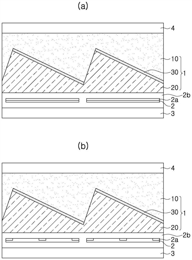
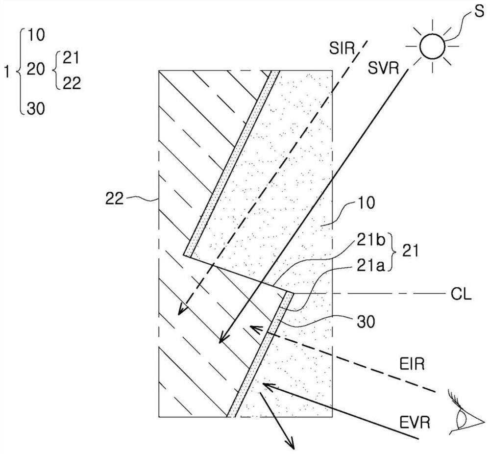
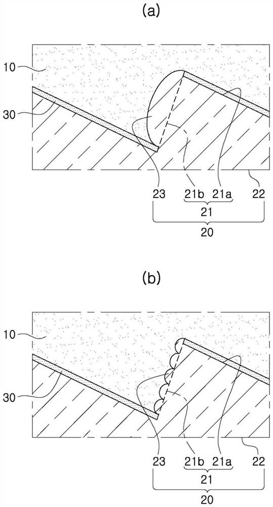
A filtering panel according to an embodiment of the present invention may comprises: a molding layer part; a pattern layer part having an incident surface through which light emitted from a light source and viewing light transmitted to an observer enter, and an accommodation surface which is the reverse surface of the incident surface, wherein the molding layer part is stacked on the incident surface so as to be adjacent thereto, and the pattern layer part adjusts the optical paths of the emitted light and the viewing light; and a filtering layer part formed on a lower incident surface of the pattern layer part having the incident surface of the viewing light that enters from a lower region below a horizontal reference line, wherein the reflectivity of the visible light in the viewing light incident on the lower region is made greater than that of an upper region above the reference line by means of mirror reflection, and the infrared light in the viewing light is allowed to pass through the filtering layer part.

Description

technical field [0001] The invention relates to a light filtering panel and a photovoltaic power generation module comprising the same. Background technique [0002] Building Integrated Photovoltaic (BIPV: Building Integrated Photovoltaic) is a system that is installed on building exterior walls, roofs, etc. and performs building exterior decoration functions while photovoltaic power generation is one of the methods that can use photovoltaic power generation in urban areas. . [0003] However, in terms of architectural design, when ordinary photovoltaic modules are directly installed on the building's exterior wall, it is difficult to ensure the aesthetics of ordinary exterior decoration materials due to the limitations of the shape of the solar cells inside the module or the black color. [0004] In response to this, techniques have been proposed to provide a color layer to the front cover glass or to control reflectivity, but there is a limitation that it is difficult to ...

Claims


Application Information

Patent Timeline
Patent Type & Authority Applications(China)
IPC IPC(8): H01L31/0216H01L31/0232H01L31/048
CPCH01L31/0549H02S40/22H01L31/054Y02E10/52H01L31/02162H01L31/02327H01L31/048H01L31/0543G02B5/208
Inventor 卓成柱白建勋金埈弘崔允桢朴智详
Owner 浦项股份有限公司
Learn More