
Hierarchical load identification system and method suitable for low-voltage transformer area

A load identification, low-voltage technology, applied in the direction of AC network circuits, electrical components, circuit devices, etc., can solve the problems of low level of user power consumption behavior collection, low level of active fault perception, confusion of connection files of line changers, etc. The effect of computing pressure and communication bandwidth occupation, expanding asset utilization, and expanding new services

Pending Publication Date: 2021-07-23
CHINA ELECTRIC POWER RES INST +5
View PDF3 Cites 0 Cited by
  • Summary
  • Abstract
  • Description
  • Claims
  • Application Information

AI Technical Summary

Problems solved by technology

[0002] With the continuous implementation of the ubiquitous power Internet of Things concept in power grid construction and the deepening of smart grid in the field of low-voltage distribution network, the intelligent sensing equipment in low-voltage station area is facing more and more new demands, while the existing low-voltage station area has long-term There is confusion in the connection files of line change households, which greatly limits the realization of functions such as line loss and power outage location. The level of fault active perception is low, fault location is inaccurate, indoor and outdoor power outages cannot be identified and the repair time is long, and the location of line loss abnormalities is automated. A series of outstanding problems such as low level and low level of user electricity consumption behavior collection

Method used


Image

  • Hierarchical load identification system and method suitable for low-voltage transformer area
  • Hierarchical load identification system and method suitable for low-voltage transformer area
  • Hierarchical load identification system and method suitable for low-voltage transformer area

Examples


Embodiment Construction

[0023] Exemplary embodiments of the present invention will now be described with reference to the drawings; however, the present invention may be embodied in many different forms and are not limited to the embodiments described herein, which are provided for the purpose of exhaustively and completely disclosing the present invention. invention and fully convey the scope of the invention to those skilled in the art. The terms used in the exemplary embodiments shown in the drawings do not limit the present invention. In the figures, the same units / elements are given the same reference numerals.

[0024] Unless otherwise specified, the terms (including scientific and technical terms) used herein have the commonly understood meanings to those skilled in the art. In addition, it can be understood that terms defined by commonly used dictionaries should be understood to have consistent meanings in the context of their related fields, and should not be understood as idealized or over...


PUM


Abstract

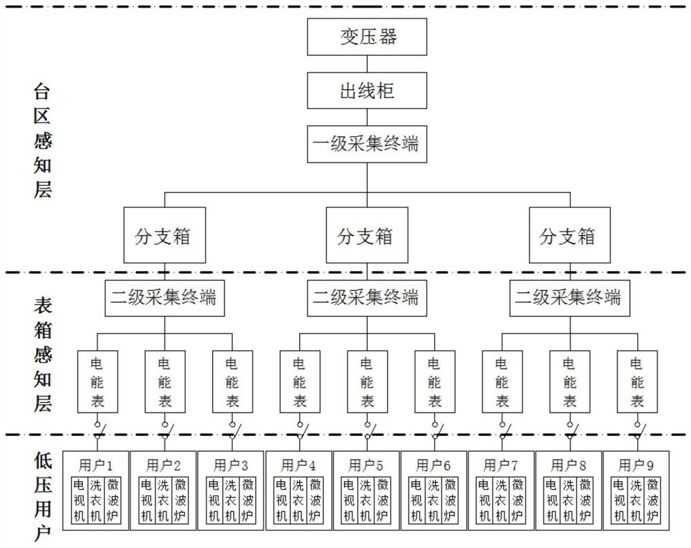
The invention discloses a hierarchical load identification system and method suitable for a low-voltage transformer area, and belongs to the technical field of advanced measurement. The system comprises a meter box sensing layer and a transformer area sensing layer, wherein the meter box sensing layer comprises an intelligent Internet of Things electric energy meter and a secondary acquisition terminal; the intelligent Internet of Things electric energy meter is connected with a low-voltage user, collects power consumption data of the low-voltage user, performs fine-grained load identification on the power consumption data, and obtains state information of the low-voltage user; the secondary acquisition terminal receives the state information acquired by the intelligent Internet of Things electric energy meter and uploads the state information to a transformer area sensing layer; the transformer area sensing layer comprises a first-level acquisition terminal; and the first-level acquisition terminal receives the state information, performs data fusion and edge computing on the state information, acquires identification data, and performs load identification by using the identification data. According to the invention, full-state sensing of the low-voltage transformer area is realized through deployment of two layers of sensing terminals.

Description

technical field [0001] The present invention relates to the field of advanced measurement technology, and more specifically, relates to a load identification system and method suitable for the stratification of low-voltage platforms. Background technique [0002] With the continuous implementation of the ubiquitous power Internet of Things concept in power grid construction and the deepening of smart grid in the field of low-voltage distribution network, the intelligent sensing equipment in low-voltage station area is facing more and more new demands, while the existing low-voltage station area has long-term There is confusion in the connection files of line change households, which greatly limits the realization of functions such as line loss and power failure location. The level of active fault perception is low, and fault location is not accurate. It is impossible to identify indoor and outdoor power failure accidents and the repair time is long. The abnormal location of l...

Claims


Application Information

Patent Timeline
IPC IPC(8): H02J3/00H02J13/00
CPCH02J3/00H02J13/00002H02J13/00032H02J13/00001H02J2310/70H02J2203/10
Inventor 刘兴奇祝恩国邹和平孙应军段梅梅夏国芳巫钟兴张宇鹏朱子旭韩月赵兵林繁涛陈昊倪斌周黎
Owner CHINA ELECTRIC POWER RES INST
Learn More