A variable structure dual-mode ram combustor

A ram combustion chamber, dual-mode technology, applied in combustion chambers, continuous combustion chambers, combustion methods, etc., can solve the problems of aircraft loss of control, thrust and momentum changes, etc., to achieve lower performance requirements, smooth transitions, and extended work Mach The effect of number range

Active Publication Date: 2022-04-26
XIAMEN UNIV +1
View PDF23 Cites 0 Cited by
  • Summary
  • Abstract
  • Description
  • Claims
  • Application Information

AI Technical Summary

Problems solved by technology

This would cause a sudden change in thrust and momentum on the vehicle, possibly causing loss of control of the vehicle

Method used


Image

  • A variable structure dual-mode ram combustor
  • A variable structure dual-mode ram combustor
  • A variable structure dual-mode ram combustor

Examples


Embodiment Construction

[0030] The following preferred embodiments of the present invention in conjunction with the accompanying drawings are described, i.e., the preferred embodiments described herein are only used to illustrate and explain the present invention, and are not intended to qualify the present invention.

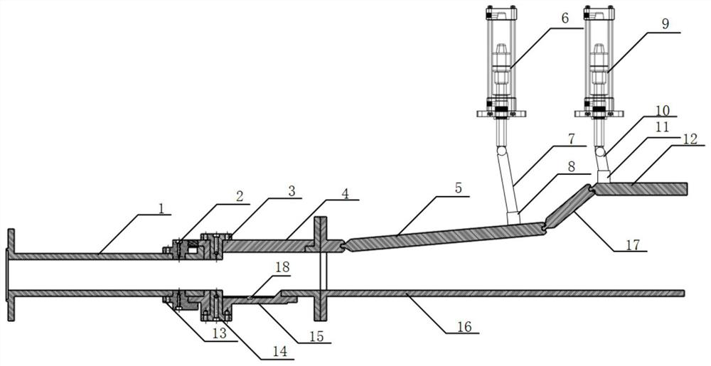
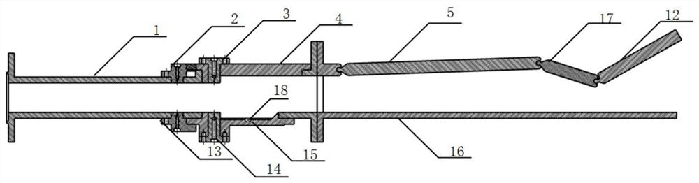
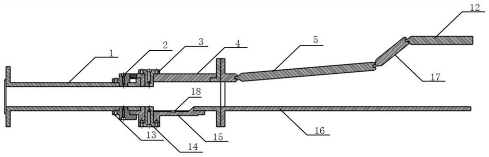
[0031] as Figures 1 to 4 As shown, embodiments of the present invention include a variable structure bimodal combustion chamber consisting of an isolation section 1, a burst expansion section 4, a cavity 15, a lower wall surface of the combustion chamber 16, a first adjustable variable 5, a second adjustable variable 17, a third adjustable variable 12 together. Isolation segments 1 and extrusion section 4 are bolted together. The upper and lower wall pioneer hydrogen injection modules 2, 13 and the upper and lower kerosene injection modules 3 and 13 are bolted to the extrusion section 4, and the first adjustable variant 5, the second adjustable variant 17, the third tunable variant 12 and...


PUM


Abstract

The utility model relates to a variable structure dual-mode ramjet combustion chamber, which relates to an aeroengine combustion chamber. Including isolation section, concave cavity, sudden expansion section, adjustable variable section, Pioneer hydrogen injection module, kerosene injection module, connecting rod and hydraulic drive; through the hydraulic connecting rod drive, the combustion chamber can be adjusted to make the combustion chamber operate at different flight Mach numbers work in different modes. 2

Description

Technical field [0001] The present invention relates to an aero engine combustion chamber, specifically to a variable structure dual-modal rammer combustion chamber with adjustable combustion chamber profile. Background [0002] When the flying Mach number Ma>3, the performance of the ramjet engine is optimal, wherein the flying Mach number Ma = 3 ~ 6, the sub-combustion ramjet engine performance is better than the super-combustion ramjet engine, and the flying Mach number Ma > At 6 o'clock, the super-fueled ramjejet engine performed better than the sub-combustion ramjet ramjet engine (Weber R J, Mackay J S. An Analysis of Ramjet EnginesUsingSupersonic Combustion[R]. NASA TN 4386,1958)。 For optimal performance, ramjet engines must operate in a dual-mode fashion. In the acceleration process of a hypersonic vehicle with a bimodal ramjet as the propulsion device, the heat release and distribution in the combustion chamber must be adjusted accordingly, so that the engine is co...

Claims


Application Information

Patent Timeline
Patent Type & Authority Patents(China)
IPC IPC(8): F23R3/28F23R3/44
CPCF23R3/286F23R3/44
Inventor 黄玥沈吴冰懿易理哲赵书苗尤延铖吴智锋
Owner XIAMEN UNIV
Why Eureka
Try Eureka