
svpwm modulation method and system for high frequency chain matrix converter

A technology of matrix converter and modulation method, applied in the direction of converter type, high-efficiency vehicle charging, high-efficiency power electronic conversion, etc., can solve problems such as magnetic saturation of transformer iron core, DC bias of transformer, and bad influence on system safety operation, etc. Achieve the effects of improving system efficiency, suppressing magnetic bias phenomenon, and preventing current bias phenomenon

Active Publication Date: 2022-07-05
SHANDONG UNIV
View PDF5 Cites 0 Cited by
  • Summary
  • Abstract
  • Description
  • Claims
  • Application Information

AI Technical Summary

Problems solved by technology

However, the improper distribution of zero vector makes the transformer current waveform asymmetric in the positive and negative half cycles, which is easy to generate DC bias of the transformer, which will lead to magnetic saturation of the transformer core in serious cases, and have a bad influence on the safe operation of the entire system

Method used


Image

  • svpwm modulation method and system for high frequency chain matrix converter
  • svpwm modulation method and system for high frequency chain matrix converter
  • svpwm modulation method and system for high frequency chain matrix converter

Examples


Embodiment 1

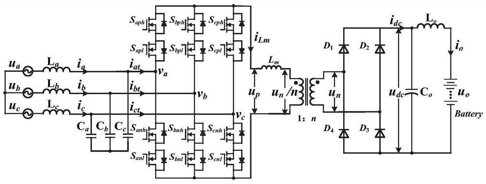
[0037] The purpose of this embodiment is to provide an SVPWM modulation method for a high-frequency chain-matrix converter.

[0038] An SVPWM modulation method for a high-frequency chain-matrix converter, comprising:

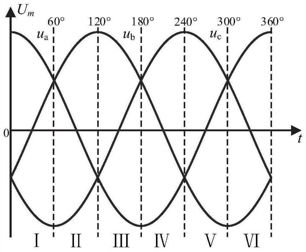
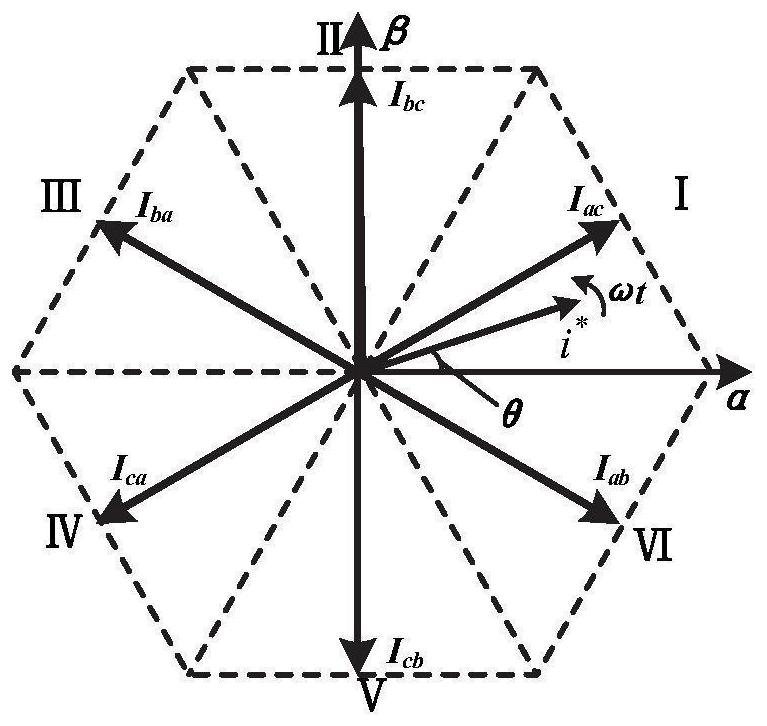
[0039] Divide the sectors according to the phase of the three-phase input voltage, and determine the vector action combination in each sector;

[0040] Calculate the action time of each vector of SVPWM without zero vector according to the action combination of each sector vector;

[0041] Determine the action sequence of each vector of zero-vector SVPWM, so that each vector acts counterclockwise one by one in the entire switching cycle;

[0042] Through the zero-vector SVPWM, an alternating positive and negative high-frequency alternating voltage is formed on the primary side of the high-frequency transformer.

[0043] For ease of understanding, the modulation method described in the present disclosure will be described in detail below with reference to the ac...

Embodiment 2

[0079] The purpose of this embodiment is to provide an SVPWM modulation system for a high-frequency chain-matrix converter.

[0080] An SVPWM modulation system for a high-frequency chain-matrix converter, comprising:

[0081] A vector action combination determination unit, which is used to divide sectors according to the three-phase input voltage phase, and determine the vector action combination in each sector;

[0082] The vector action time determining unit is used to calculate the action time of each vector of the zero-vector SVPWM according to the combination of the vector actions of each sector;

[0083] The vector action sequence determination unit is used to determine the action sequence of each vector of the zero-vector SVPWM, so that each vector acts counterclockwise one by one in the entire switching cycle;

[0084] The SVPWM modulation unit is used to form a high-frequency alternating voltage with alternating positive and negative on the primary side of the high-f...


PUM


Abstract

The present disclosure provides an SVPWM modulation method and system for a high-frequency chain-matrix converter. The solution uses three effective vectors to accurately synthesize a reference vector within one switching cycle, without the need for zero-vector action, ensuring that the transformer current waveform is symmetrical and can be Effectively prevent the transformer current bias phenomenon; at the same time, based on the proposed zero-vector SVPWM modulation, by designing the vector action sequence and the start / stop vector, the vector switching can be guaranteed at any time including sector switching. Only one switch tube is actuated, which improves the system efficiency; and the modulation strategy described in the present disclosure has no DC current bias on the primary side of the transformer, which effectively suppresses the phenomenon of transformer bias.

Description

technical field [0001] The present disclosure belongs to the technical field of high-frequency chain-matrix converter modulation, and in particular, relates to an SVPWM modulation method and system for a high-frequency chain-matrix converter. Background technique [0002] The statements in this section merely provide background information related to the present disclosure and do not necessarily constitute prior art. [0003] The charging system is an indispensable infrastructure in the field of electric vehicles. Existing electric vehicle charging systems often use multi-level power conversion topologies, which are bulky and have low energy utilization. The high-frequency chain-matrix converter adopts a single-stage topology, which has the advantages of high energy density, input and output isolation, and reliable operation, and has broad application prospects in the field of electric vehicle charging systems. [0004] The high-frequency transformer is an important part o...

Claims


Application Information

Patent Timeline
Patent Type & Authority Patents(China)
IPC IPC(8): H02M5/293H02J7/10B60L53/00
CPCH02M5/293H02J7/06B60L53/00H02J2207/20B60L2210/22B60L2210/30Y02T10/92
Inventor 段彬李祥杰张承慧宋金秋姜昆万东祥
Owner SHANDONG UNIV
Learn More