
Laparoscope assembly and using method

A technology of laparoscopy and components, applied in the field of medical devices, can solve problems such as complicated operation and waste of medical devices, achieve simple and convenient operation, and improve the effect of observation clarity

Pending Publication Date: 2021-07-16
甘肃省武威肿瘤医院
View PDF0 Cites 1 Cited by
  • Summary
  • Abstract
  • Description
  • Claims
  • Application Information

AI Technical Summary

Problems solved by technology

[0003] However, in the existing laparoscope assembly, the lens and the introduction tube are integrated. When the lens needs to be replaced, the entire laparoscope assembly needs to be replaced as a whole, which is not only complicated to operate, but also causes waste of medical equipment.

Method used


Image

  • Laparoscope assembly and using method
  • Laparoscope assembly and using method
  • Laparoscope assembly and using method

Examples


Embodiment 1

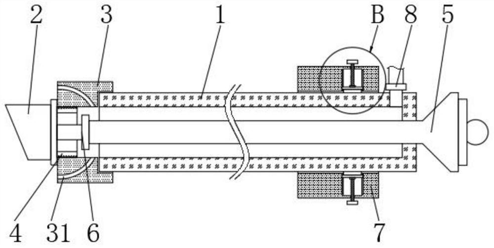
[0037] see figure 1 , image 3 , Figure 4 , Figure 7 and Figure 8 , the present embodiment provides a laparoscope assembly, including an introduction tube 1, a lens 2, and an installation sleeve 3 fixedly installed at the end of the introduction tube 1, and the installation sleeve 3 is welded and connected to the end of the introduction tube 1, which is convenient for aligning the lens 2 to install.

[0038] One end of the lens 2 is fixedly connected with a connection sleeve 4, the outer diameter of the connection sleeve 4 matches the inner diameter of the installation sleeve 3, and the connection sleeve 4 is fixedly arranged in the installation sleeve 3, by installing the connection sleeve 4 on After being installed in the sleeve 3, the lens 2 can be fixedly installed at the end of the introduction tube 1, so that the introduction tube 1 can send the lens 2 into the abdominal cavity of the patient.

[0039] Such as image 3 As shown, the connecting sleeve 4 is screwe...

Embodiment 2

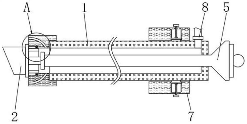
[0056] refer to Figure 2-3 and Figure 5-6 , the difference from Example 1 is:

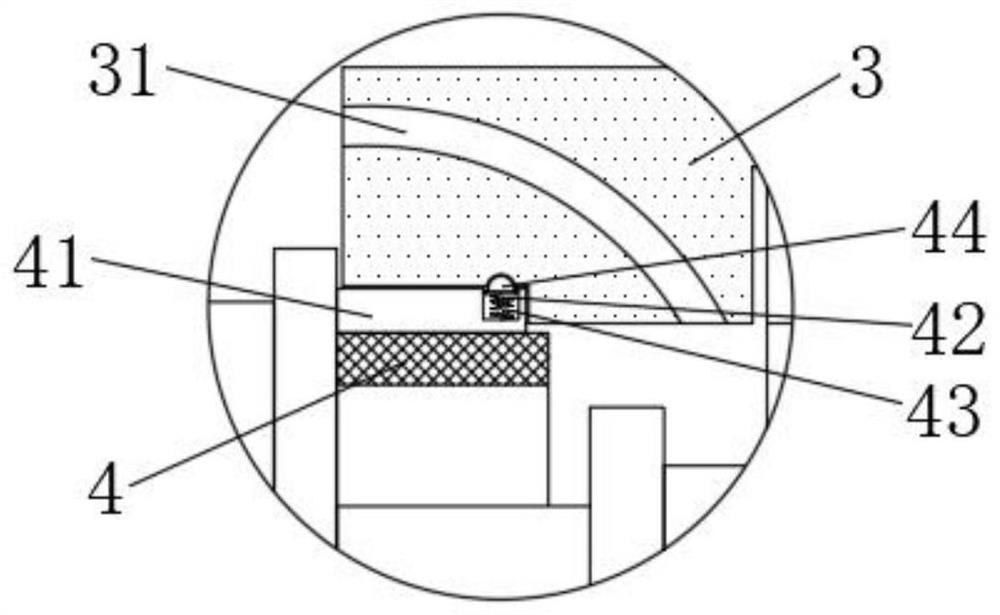
[0057] The connecting sleeve 4 is clamped in the installation sleeve 3, and the outer wall of the connection sleeve 4 is fixedly connected with a rectangular strip 41, and the inner wall of the installation sleeve 3 is provided with a strip-shaped slot matching the shape of the rectangular strip 41. The strip 41 cooperates with the strip-shaped slot, so that the connecting sleeve 4 can be inserted into the installation sleeve 3 smoothly, and the connection sleeve 4 and the installation sleeve 3 are conveniently engaged with each other.

[0058] One side of the rectangular bar 41 away from the connecting sleeve 4 is provided with a mounting groove 42, a spring 43 is fixedly connected in the mounting groove 42, and the end of the spring 43 is fixedly connected with a block 44. Block 44 matching slot, block 44 will move to the side wall direction of installation sleeve 3 under the elastic effect o...


PUM


Abstract

The invention discloses a laparoscope assembly and a using method, and relates to the field of medical instruments. The laparoscope assembly comprises a lead-in pipe, a lens and an installation sleeve fixedly installed at the tail end of the lead-in pipe; one end of the lens is fixedly connected with a connecting sleeve; the connecting sleeve is fixedly arranged in the installation sleeve; a heat conduction rod connected with the lens is arranged in the connecting sleeve; and one end, away from the lens, of the heat conduction rod is fixedly connected with a heating element. According to the invention, the lens is installed on the connecting sleeve; furthermore, the connecting sleeve can be in threaded connection or clamped connection with the installation sleeve at the tail end of the lead-in pipe, so that the lens can be quickly replaced according to operation requirements before an operation; therefore, the abdomen of a patient can be observed at different angles; the operation is simple and convenient; and in addition, through a supporting sleeve and a lead screw, a rectangular plate and a clamping piece arranged in the supporting sleeve, the lead-in pipe can be fixed, so that the lens at the tail end of the lead-in pipe can be stably arranged in the abdominal cavity of the patient, and the lens is more stable during observation.

Description

technical field [0001] The invention relates to the technical field of medical devices, in particular to a laparoscope assembly and a method for using it. Background technique [0002] Laparoscope is similar to electronic gastroscope. It is a medical device with a miniature camera. It is an important medical device in laparoscopic surgery. Before laparoscopic surgery, each patient needs to use a different Therefore, it is necessary to select different laparoscopic lenses according to the surgical requirements before the operation. [0003] However, in the existing laparoscope assembly, the lens and the introduction tube are integrated. When the lens needs to be replaced, the entire laparoscope assembly needs to be replaced as a whole, which is not only complicated to operate, but also causes waste of medical equipment. Contents of the invention [0004] The object of the present invention is to provide a laparoscope assembly and a method of use, so as to solve the problem...

Claims


Application Information

Patent Timeline
IPC IPC(8): A61B1/313A61B1/12A61B17/02A61B1/00
CPCA61B1/00121A61B1/127A61B1/313A61B17/02
Inventor 安存莲毛鹏郭玮
Owner 甘肃省武威肿瘤医院
Learn More