Rigid-flexible coupling fire blast driver and driving method

A rigid-flexible coupling and driver technology, which is used in earth-moving drilling, fluid production, wellbore/well components, etc., can solve the problems of poor controllability of energy release direction and low instantaneous acceleration, and achieve light weight, high safety, Material saving effect

Active Publication Date: 2021-07-13
HARBIN INST OF TECH
View PDF12 Cites 0 Cited by
  • Summary
  • Abstract
  • Description
  • Claims
  • Application Information

AI Technical Summary

Problems solved by technology

[0004] The object of the present invention is to solve the problems of low instantaneous acceleration and poor controllability of energy release direction in the existing soft drive, and provide a rigid-flexible coupling detonation drive and drive method

Method used


Image

  • Rigid-flexible coupling fire blast driver and driving method
  • Rigid-flexible coupling fire blast driver and driving method

Examples


specific Embodiment approach 1

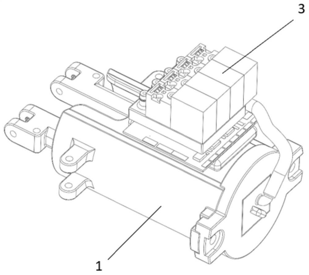
[0025] Specific implementation mode one: the following combination figure 1 and figure 2 This embodiment is described. A rigid-flexible coupling detonation driver described in this embodiment includes a rigid piston assembly 1, a soft detonation chamber 2 and a control unit 3. The control unit 3 transports combustible gas into the soft detonation chamber 2. The soft explosion chamber 2 is made of silica gel casting. The soft explosion chamber 2 bears the explosion power and converts the explosion energy into mechanical energy through expansion. The mechanical energy is linearly output by pushing the rigid piston assembly 1 to move.

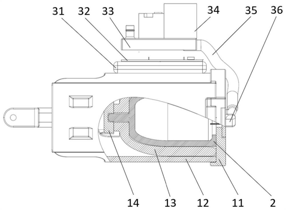
[0026] The rigid piston assembly 1 includes a cylinder body 12, a rigid piston 13, a rear end cover 11 and a power output part 14, the rear end opening of the cylinder body 12 is provided with a rear end cover 11, and the rear end cover 11 and the cylinder body 12 are connected by bolts. Connection, the rigid piston 13 is arranged in the cylinde...

specific Embodiment approach 2

[0035] Specific embodiment two: a driving method of a rigid-flexible coupling detonation driver described in this embodiment, the method is implemented based on a rigid-flexible coupling detonation driver described in the first embodiment, and the method includes the following steps:

[0036] S1, air extraction: through the circuit board 32 to control the valve island 33 to drain the gas in the software explosion chamber 2;

[0037] S2. Inflating: filling the combustible gas mixed with the valve island 33 into the soft explosion chamber 2;

[0038] S3. Ignition: control the discharge of the ignition head 36 through the circuit board 32, and ignite and explode the combustible gas filled in the soft explosion chamber 2;

[0039] S4. Energy output / conversion: the gas explosion causes the soft explosion chamber 2 to expand, and under the constraints of the rigid piston 13 and the cylinder body 12, the expanded soft explosion chamber 2 pushes the rigid piston 13 to make a linear mo...


PUM


Abstract

The invention discloses a rigid-flexible coupling fire blast driver and a driving method, belongs to the field of driving of jumping robots, and aims at solving the problems that an existing soft driver is low in instantaneous acceleration and poor in controllability of the energy release direction. The driver comprises a rigid piston assembly, a soft combustion and explosion cavity and a control unit. The driving method comprises the steps that S1, air exhaust is conducted, specifically, air in the soft combustion and explosion cavity is exhausted through a circuit board control valve terminal; S2, inflation is conducted, specifically, combustible gas mixed through a valve terminal in a matching mode is inflated into a soft burning and explosion cavity; S3, ignition is conducted, specifically, an ignition head is controlled to discharge through a circuit board, and combustible gas filled into the soft combustion and explosion cavity is ignited and exploded; S4, gas explosion enables the soft combustion and explosion cavity to expand, a rigid piston is pushed to do linear motion in a cylinder body, and the power output part linearly outputs energy; S5, returning is conducted, specifically, after the explosion is finished, the internal pressure of the soft combustion and explosion cavity is instantaneously reduced, the soft combustion and explosion cavity shrinks, and the rigid piston is pulled back to the initial position; and the steps S2-S5 are repeatedly executed, and the rigid piston reciprocates in the cylinder body.

Description

technical field [0001] The invention belongs to the driving field of jumping robots. Background technique [0002] Software driver technology has a wide range of applications in the field of soft robots. Compared with traditional rigid robot drives, soft drives have higher adaptability to complex environments and higher safety in human-computer interaction. [0003] Existing actuators for soft bouncing robots include the frog-like underwater soft robot driven by chemical exothermic reactions Jiao, et al., 2020, flexible detonation fracturing devices and drilling strings (Zhang, et al., 2019), and A magnetically actuated jumping soft robot based on a magnetically programmed thermosensitive hydrogel (Lin, et al., 2020). The main disadvantages of these soft drives are low instantaneous acceleration, poor controllability of energy release direction, etc. Contents of the invention [0004] The purpose of the present invention is to solve the problems of low instantaneous acc...

Claims


Application Information

Patent Timeline
Patent Type & Authority Applications(China)
IPC IPC(8): E21B43/247
CPCE21B43/247
Inventor 樊继壮喻曦高峰马维良赵杰
Owner HARBIN INST OF TECH
Why Eureka
Try Eureka