Non-floor dynamic height-adjusting support and construction method for steel plate composite girder bridge deck construction

A technology of composite beams and steel plates, which is applied in bridges, bridge construction, erection/assembly of bridges, etc., can solve the problems of inability to adjust dynamically and in real time, and inconvenient erection of floor supports, so as to achieve easy control of construction quality, easy operation of adjustment and dismantling, and The effect of simple construction technology

Active Publication Date: 2022-08-05
CHANGAN UNIV
View PDF6 Cites 0 Cited by
  • Summary
  • Abstract
  • Description
  • Claims
  • Application Information

AI Technical Summary

Problems solved by technology

[0004] In view of the deficiencies in the prior art, the object of the present invention is to provide a non-ground dynamic height-adjusting bracket and construction method for steel plate composite beam bridge deck construction, so as to solve the inconvenience of erecting the floor support during the construction process of the steel plate composite beam in the prior art and the problem of being unable to dynamically adjust in real time

Method used


Image

  • Non-floor dynamic height-adjusting support and construction method for steel plate composite girder bridge deck construction
  • Non-floor dynamic height-adjusting support and construction method for steel plate composite girder bridge deck construction
  • Non-floor dynamic height-adjusting support and construction method for steel plate composite girder bridge deck construction

Examples


Embodiment 1

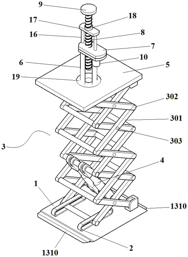
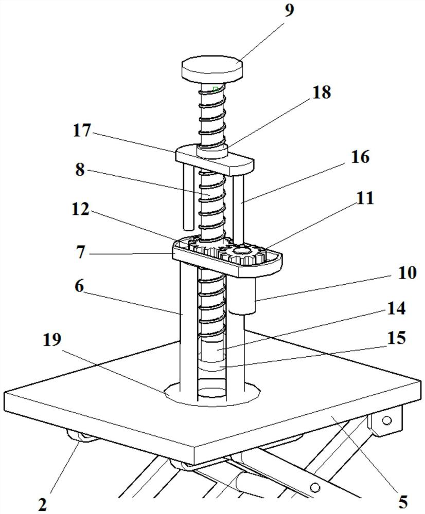
[0042] This embodiment provides a non-floor dynamic height-adjusting bracket for the construction of steel plate composite girder bridge deck, such as Figure 1 to Figure 3As shown, including the lower platform 1 for linkage work, the lower platform 1 for linkage work is fixedly provided with a scissor bar restraint rail 2, and the scissor bar restraint rail 2 is installed with a scissor bar lift that can move in the scissor bar restraint rail 2 One end of the bottom of the assembly 3, the other end of the bottom of the scissor lift assembly 3 is hinged on the lower platform 1 for linkage work; the lower platform 1 for linkage work is also installed with the tail end of the electro-hydraulic telescopic rod 4, and the head of the electro-hydraulic telescopic rod 4 The end is connected to the scissor bar lifting assembly 3 to drive the lifting and lowering of the scissor bar lifting assembly 3; the top end of the scissor bar lifting assembly 3 is installed in the scissor bar rest...

Embodiment 2

[0057] The present embodiment provides a construction method for a steel plate composite girder bridge deck that does not fall to the ground, and the method adopts the non-falling dynamic height-adjusting bracket for the construction of a steel plate composite girder bridge deck in Example 1;

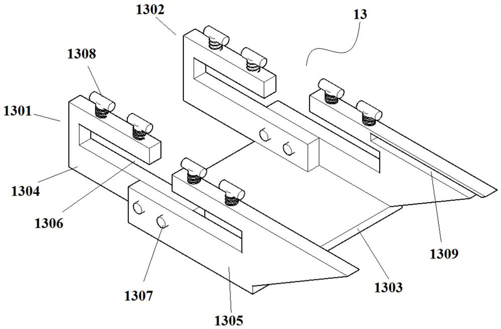
[0058] like Figure 4 and Figure 5 As shown, on the I-beam 20 of the steel plate composite beam 21, a plurality of non-floor dynamic height-adjusting brackets are installed for the construction of the steel plate composite beam bridge deck, and the linkage work at the bottom of the non-floor dynamic height-adjusting bracket for the construction of each steel plate composite girder bridge deck is used. The lower platform 1 is installed on the wing plates on both sides of the I-beam 20 of the steel plate composite beam 21 through the I-beam fasteners 13, and the formwork pedestal 9 on the top of the non-floor dynamic height-adjusting bracket is used for the construction of each steel pla...


PUM


Abstract

The invention provides a non-falling dynamic height-adjusting support for steel plate composite girder bridge deck construction and a construction method, including a linkage working lower platform, the bottom of the scissor bar lifting assembly is arranged on the linkage working lower platform; A linkage work upper platform is installed on the top; a telescopic cylinder is installed vertically on the linkage work upper platform, a gear box is installed on the top of the telescopic cylinder, and a screw that penetrates the telescopic cylinder and the gear box at the top is installed in the telescopic cylinder. The top is provided with a template pedestal; a motor is installed on the gear box, the rotation of the motor drives the driven gear to rotate with the vertical axis as the rotation axis, and the driven gear rotates with the vertical axis as the rotation axis to drive the screw to rise and fall vertically. The bracket of the present invention can complete the initial elevation adjustment through the scissor-type electric lifting linkage platform, and can realize the precise elevation adjustment through the dynamic and precise adjustment of the screw lifting and lowering by the motor. The two elevation adjustment modes can accurately complete the template elevation adjustment and realize dynamic adjustment. .

Description

technical field [0001] The invention belongs to the field of roads and bridges, and relates to the construction of steel plate composite girder bridge decks, in particular to a non-floor dynamic height-adjusting bracket and a construction method for the construction of steel plate composite girder bridge decks. Background technique [0002] The steel-concrete composite structure makes full use of the respective material properties of steel and concrete, and has the advantages of light weight, high bearing capacity, high rigidity, good seismic performance and dynamic performance, small section size of components, and fast and convenient construction. Over the years, it has been fully applied in bridge engineering, especially in municipal bridges. [0003] The construction of steel plate composite beams is usually by assembling prefabricated steel beam segments on site. The prefabricated concrete slab only needs to pour concrete at the reserved slot, which reduces the workloa...

Claims


Application Information

Patent Timeline
Patent Type & Authority Patents(China)
IPC IPC(8): E01D21/00
CPCE01D21/00
Inventor 王晓明赵建领李鹏飞汪帆祁泽中陶沛
Owner CHANGAN UNIV
Why Eureka
Try Eureka