
Air conditioner and control method thereof

A control method and air conditioner technology, which is applied to air conditioning systems, airflow control components, heating methods, etc., and can solve problems such as poor air supply effects of air conditioners

Active Publication Date: 2021-07-06
ZHUHAI GREE REFRIGERATION TECH CENT OF ENERGY SAVING & ENVIRONMENTAL PROTECTION
View PDF4 Cites 4 Cited by
  • Summary
  • Abstract
  • Description
  • Claims
  • Application Information

AI Technical Summary

Problems solved by technology

[0003] In view of this, the present invention discloses an air conditioner and its control method to at least solve the problem of poor air supply effect of existing air conditioners

Method used


Image

  • Air conditioner and control method thereof
  • Air conditioner and control method thereof
  • Air conditioner and control method thereof

Examples


Embodiment 1

[0041] An air conditioner is provided in this embodiment, and the air conditioner includes:

[0042] A casing, the casing has an air outlet 12;

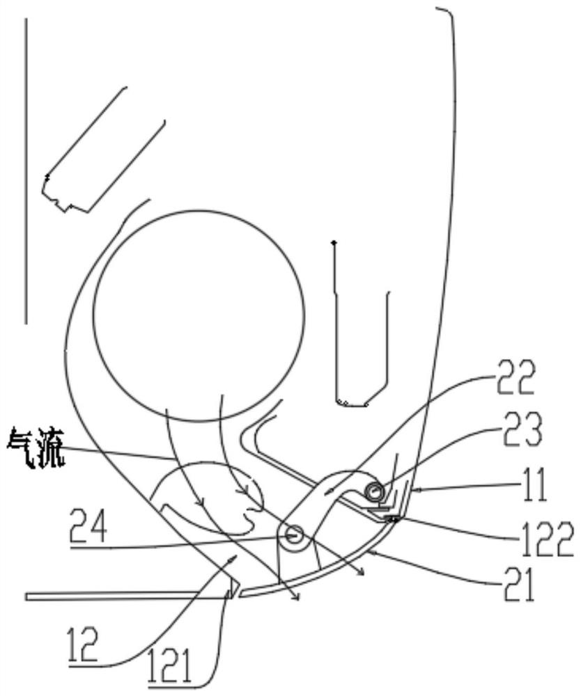
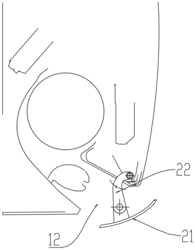
[0043] The wind guide assembly, the wind guide assembly includes: a wind guide plate 21, the wind guide plate 21 is rotatably arranged at the air outlet 12, and the wind guide plate 21 has a function on its rotation path to prevent the wind guide plate 21 from colliding with the air outlet 12. Avoidance position; transmission rod assembly, the first end of the transmission rod assembly is rotatably connected to the wind deflector 21 to make the wind deflector 21 rotate, and the second end of the transmission rod assembly is rotatably connected to the air outlet 12 to drive the wind deflector 21 for revolution.

[0044] The process of autorotation includes: before the wind guide assembly is opened, the wind guide plate 21 rotates around the first end of the transmission rod assembly at the air outlet 12 to the avoidance position; Th...

Embodiment 2

[0050] In this embodiment, a control method of an air conditioner is provided, and the control method is used to control any air conditioner in Embodiment 1 to guide air.

[0051] The control method includes: during the start-up process of the air conditioner, driving the air deflector 21 to rotate so that the tail of the air deflector rotates toward the inner side of the air outlet 12 of the air conditioner to an avoidance position; The outer side of the tuyere 12 rotates; when the transmission rod assembly drives the wind deflector 21 to rotate to a preset wind deflecting position, the wind deflector 21 is driven to rotate according to a preset opening angle to realize wind deflection. Optionally, during the closing process of the air conditioner, the air conditioner controls the transmission rod assembly and the air guide plate 21 to perform a reverse process of the opening process to close the air guide assembly.

[0052] Because the air conditioner in this embodiment has ...


PUM


Abstract

The invention discloses an air conditioner and a control method thereof. The air conditioner comprises a shell, an air guide assembly and a transmission rod assembly, wherein the shell is provided with an air outlet; the air guide assembly comprises an air guide plate, the air guide plate is rotatably arranged at the air outlet, and an avoiding position for preventing the air guide plate from colliding with the air outlet is arranged on the rotating path of the air guide plate; a first end of the transmission rod assembly is rotatably connected with the air guide plate to enable the air guide plate to rotate, and a second end of the transmission rod assembly is rotatably connected with the air outlet to drive the air guide plate to revolve; the rotation comprises the steps that before the air guide assembly is started, the air guide plate rotates to the avoiding position at the air outlet around the first end of the transmission rod assembly, and after the air guide assembly is started, the air guide plate rotates to a preset air guide position at the air outlet around the first end of the transmission rod assembly; and the revolution comprises the step that in the starting / stopping process of the air guide assembly, the transmission rod assembly drives the air guide plate to rotate around the second end of the transmission rod assembly to a preset air swinging position at the air outlet.

Description

technical field [0001] The present invention relates to the related technical field of air conditioners, in particular to an air conditioner and a control method thereof. Background technique [0002] At present, most of the air deflectors at the air outlet of the air conditioner on the market are directly driven by the motor to drive the air deflector to operate to realize the function of air deflector and air supply, and the driving mechanism of the air deflector is mostly placed on the lower edge of the air outlet of the air conditioner. The operation and control mode of the wind deflector in this method is simple, and the functional requirements of the multi-directional rotation of the wind deflector cannot be realized, and the air supply effect is poor and the sweeping range is small. Contents of the invention [0003] In view of this, the present invention discloses an air conditioner and a control method thereof, which are used to at least solve the problem of poor ...

Claims


Application Information

Patent Timeline
IPC IPC(8): F24F1/0011F24F13/14F24F11/79F24F11/64
CPCF24F1/0011F24F13/14F24F13/1426F24F11/79F24F11/64F24F2013/1446
Inventor 刘慧杨永祥周文伟王现林潘正伟洪丽
Owner ZHUHAI GREE REFRIGERATION TECH CENT OF ENERGY SAVING & ENVIRONMENTAL PROTECTION
Learn More