
Active pneumatic wing fence rod structure and control method thereof

An active and aerodynamic technology, applied in the field of active aerodynamic wing fence pole structure and its control, can solve the problems of reducing wind vibration performance and failing to meet the wind vibration performance requirements of long-span bridges

Active Publication Date: 2021-07-06
TONGJI UNIV
View PDF8 Cites 0 Cited by
  • Summary
  • Abstract
  • Description
  • Claims
  • Application Information

AI Technical Summary

Problems solved by technology

[0004] However, with the increase of the bridge span, the improvement effect that passive aerodynamic measures can provide is approaching the limit, and most passive aerodynamic measures cannot take into account a variety of adverse wind-induced vibration effects, and some measures can improve a certain type of wind-induced vibration performance. At the same time, it will even reduce other wind-induced vibration performance, and simply using traditional passive aerodynamic measures can no longer meet the wind-induced vibration performance requirements of long-span bridges

Method used


Image

  • Active pneumatic wing fence rod structure and control method thereof
  • Active pneumatic wing fence rod structure and control method thereof
  • Active pneumatic wing fence rod structure and control method thereof

Examples


Embodiment 1

[0050]Super-long-span suspension bridges are more and more widely used in the field of sea-crossing engineering. The natural conditions they face are complex and changeable, especially for extreme weather such as typhoons. Traditional passive aerodynamic measures can only be used at a certain wind angle of attack and If it works in the low wind speed range, the wind vibration control effect it can provide is often limited, and various measures cannot take into account various wind vibration phenomena. On the other hand, the vibration suppression effect of passive aerodynamic measures is usually determined by wind tunnel tests, which are limited by factors such as the size of the wind tunnel. Can not fully play its intended effect.

[0051] Active flap measures can adjust the spatial attitude and operating state of the device in real time according to the specific form of bridge wind vibration, and realize bridge wind-induced vibration control in a more active way. It has the a...


PUM

PropertyMeasurementUnit
Heightaaaaaaaaaa
Widthaaaaaaaaaa

Abstract

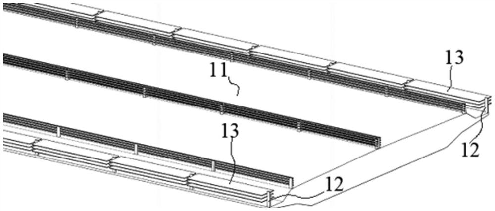
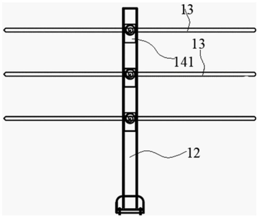
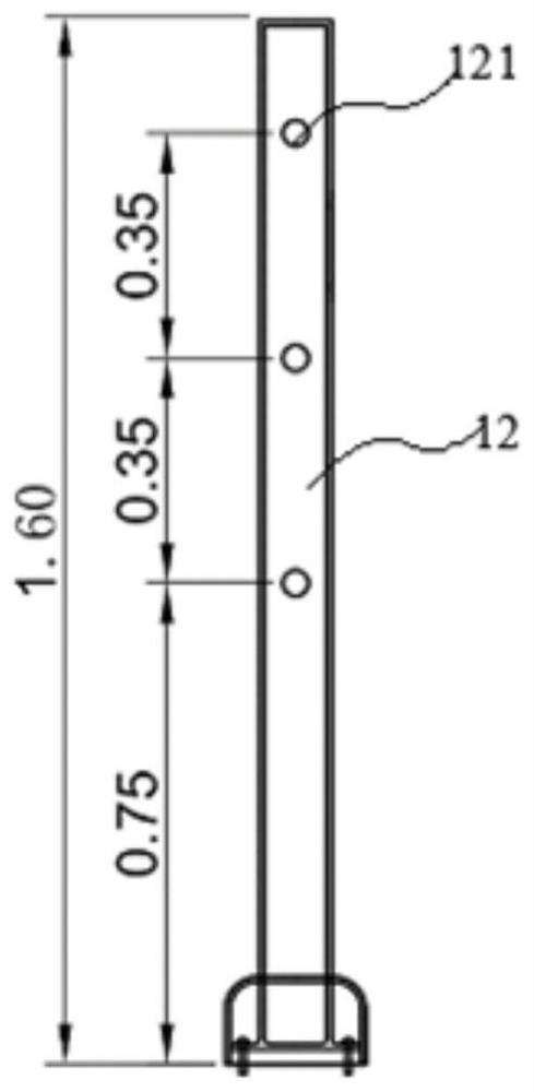
The invention provides an active pneumatic wing fence rod structure and a control method thereof, and relates to the technical field of large-span bridge wind vibration performance. The active pneumatic wing fence rod structure comprises a main beam, side handrails, pneumatic wing plates and a driving mechanism. The side handrails are arranged on the edges of the main beam, and a plurality of pneumatic wing plates are arranged between any two adjacent side handrails. The posture of the pneumatic wing plate can be adjusted in real time along with changes of the wind environment where the bridge is located and the vibration state of the main beam, so that the pneumatic lifting torque of the bridge is reduced, and the wind vibration performance of the bridge structure is improved. The control method comprises the following steps: setting a function of torsion motion of the main beam; deriving a function of torsional acceleration of the main beam from the function of torsional motion of the main beam; selecting the phase difference of motion between the pneumatic wing plates and the main beam and the amplification coefficient from the amplitude of the main beam to the amplitudes of the pneumatic wing plates as control parameters; exporting a torsional motion function form of the pneumatic wing plates; and controlling the rotation of the pneumatic wing plates according to the torsional motion function form of the pneumatic wing plates.

Description

technical field [0001] The invention relates to the technical field of wind vibration performance of long-span bridges, in particular to an active aerodynamic wing fence pole structure and a control method thereof. Background technique [0002] The aerodynamic performance of long-span bridges mainly depends on the surface aerodynamic force on the main girder, and the aerodynamic force of the main girder is closely related to the flow pattern of the flow field around the main girder. The shape of the main girder is the key factor determining the shape of its surface flow field . [0003] In order to improve the wind vibration performance of bridge structures, such as increasing the critical wind speed of flutter, reducing the amplitude of vortex vibration and buffeting vibration, aerodynamic control measures are usually added on the surface, such as deflectors, damping plates, central slots, Skirts, splitters, nozzles and stabilizers, etc. They are usually fixed to the brid...

Claims


Application Information

Patent Timeline
IPC IPC(8): E01D19/10E01D19/00
CPCE01D19/103E01D19/00Y02E10/72
Inventor 王子龙方根深赵林陈翰林葛耀君
Owner TONGJI UNIV
Learn More