Automatic sand core taking and repairing mechanism

An automatic, sand-core technology, applied in the field of foundry repair, can solve the problems of increased production cost, long time consumption, waste of production waiting, etc.

Pending Publication Date: 2021-07-06
ANHUI QUANCHAI TIANHE MACHINERY
View PDF0 Cites 0 Cited by
  • Summary
  • Abstract
  • Description
  • Claims
  • Application Information

AI Technical Summary

Problems solved by technology

Due to automatic production, the existing technology uses manual repairing of sand cores, which has high labor intensity and takes a long time, resulting in waste of production waiting in the upper and lower processes; it takes a long time to manually repair the core on the mold, which affects production efficiency and causes The production cost increases; secondly, when manually repairing the drape of the sand core, only the drape that can be seen and reached can be repaired, and the drape close to the tire surface cannot be repaired, and the missed repair of the drape will cause cracks and blisters in the casting defects, resulting in product scrapping
In order to solve the problem of product defects and production line efficiency improvement caused by sand core slits, it is necessary to design a device that can automatically remove and repair cores to ensure product quality and improve production line efficiency. For this reason, we propose a sand core The automatic repair mechanism is used to solve the above problems

Method used


Image

  • Automatic sand core taking and repairing mechanism
  • Automatic sand core taking and repairing mechanism
  • Automatic sand core taking and repairing mechanism

Examples


Embodiment Construction

[0015] The following will clearly and completely describe the technical solutions in the embodiments of the present invention with reference to the accompanying drawings in the embodiments of the present invention. Obviously, the described embodiments are only some, not all, embodiments of the present invention. Based on the embodiments of the present invention, all other embodiments obtained by persons of ordinary skill in the art without making creative efforts belong to the protection scope of the present invention.

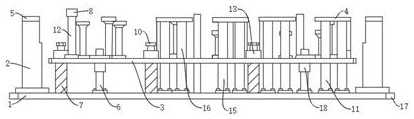
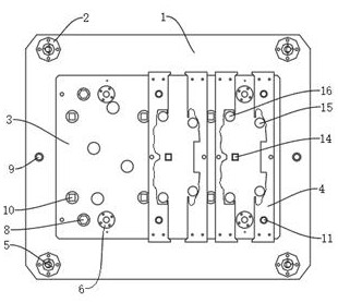
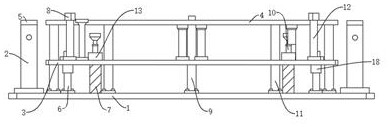
[0016] see Figure 1-3 , the present invention provides a technical solution: an automatic sand core repair mechanism, including a bottom plate 1, positioning pillars 2 are fixedly installed at the four corners of the top of the bottom plate 1, a positioning sleeve 5 is fixedly installed on the top of the positioning pillar 2, and the top of the bottom plate 1 The middle part of one side is fixedly equipped with a positioning sleeve 9, and one side of the posi...


PUM


Abstract

The invention discloses an automatic sand core taking and repairing mechanism. The automatic sand core taking and repairing mechanism comprises a bottom plate, positioning supporting columns are fixedly installed at the four corners of the top of the bottom plate, positioning sleeves are fixedly installed at the tops of the positioning supporting columns, a positioning sleeve is fixedly installed in the middle of one side of the top of the bottom plate, a spring rod is fixedly installed on one side of each positioning sleeve, each spring rod is coaxially and movably sleeved with a reset spring, the bottom ends of the reset springs are fixedly installed on the bottom plate, the top ends of the reset springs are in friction connection with a floating plate, spring housings are fixedly installed at the top of the floating plate and coaxially and fixedly installed at the upper ends of the spring rods, a limiting block is fixedly arranged on the side, away from the corresponding positioning sleeve, of each spring rod, a limiting rod is coaxially and fixedly installed at the bottom of each limiting block, the bottoms of the limiting rods are fixedly installed on the top of the floating plate, a guide column is arranged on one side of each limiting block, the bottoms of the guide columns are fixedly installed on the top of the bottom plate, the upper ends of the guide columns are coaxially and slidably sleeved with linear bearings, the linear bearings are fixedly installed on the floating plate, and a plurality of core finishing plates are fixedly arranged on one sides of the guide columns.

Description

technical field [0001] The invention relates to the field of casting repair technology, in particular to an automatic sand core repair mechanism. Background technique [0002] Cold box casting is a widely used casting process. Compared with other processes, it has the characteristics of high production efficiency, short production cycle, easy mechanization and automation, and low material cost. The process can be roughly divided into core making, Core repairing, coating dipping, drying, assembly (modeling, core laying, box closing), pouring, etc. In the production line with high degree of automatic production, the process of core making, core repairing and core assembly is that after the sand core is made by the core making mechanism, the upper and lower molds are opened, the sand core remains on the upper mold, and then the lower mold exits the coring mechanism and enters, and the upper mold enters. The mold descends to take the sand core off the coring mechanism. After t...

Claims


Application Information

Patent Timeline
IPC IPC(8): B22C9/18
CPCB22C9/18
Inventor 满鹏
Owner ANHUI QUANCHAI TIANHE MACHINERY
Why Eureka
Try Eureka