


Quick Research
Generate reliable direction feasibility study reports for your R&D in just a few steps.

Technical Q&A
Discover and master advanced knowledge NOW. Basics, ideas, possibilities, all at once.

Find Solutions
As an expert in R&D theories, this can generate solutions to your technical problems instantly.

Evaluate Feasibility
Analyze your overall solution with one click, know your potential R&D risks in advance.

Monitor Landscape
Get weekly tech updates, stay abreast of the latest tech innovations and key insights.
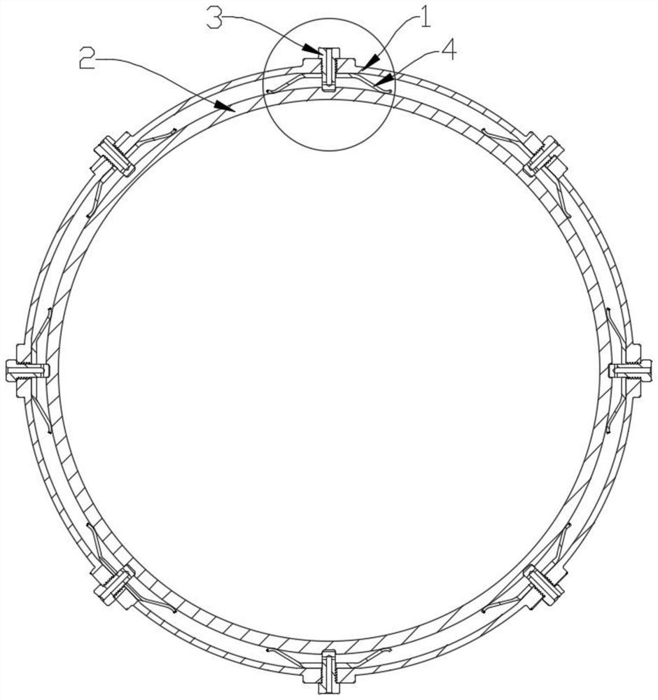
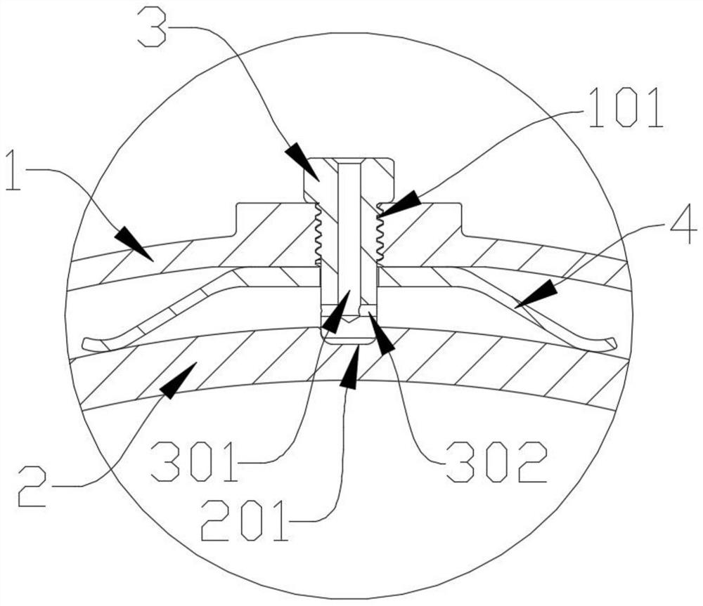
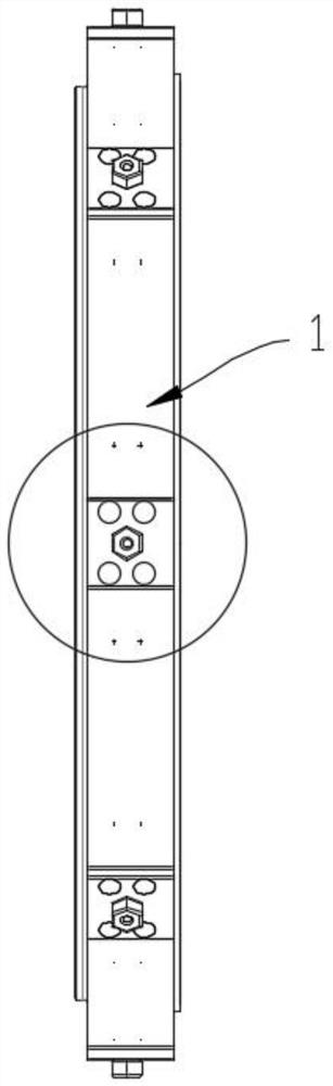
Centering and positioning structure for CMC gas turbine outer ring
A centering positioning and gas turbine technology, which is applied in the direction of climate sustainability, sustainable transportation, machines/engines, etc., can solve the problems of limited spring volume, uneven expansion, and reduced elastic modulus, and achieves convenient and good assembly. Distribution of contact force and the effect of reducing the temperature of shrapnel
- Summary
- Abstract
- Description
- Claims
- Application Information
AI Technical Summary
Problems solved by technology
Method used
Image

Examples
Embodiment Construction
[0031] In order to make the objectives, technical solutions and advantages of the present invention more clearly understood, the technical solutions of the present invention will be further specifically described below through embodiments and in conjunction with the accompanying drawings. In the specification, the same or similar reference numerals refer to the same or similar parts. The following description of the embodiments of the present invention with reference to the accompanying drawings is intended to explain the general inventive concept of the present invention, and should not be construed as a limitation of the present invention.
[0032] Furthermore, in the following detailed description, for convenience of explanation, numerous specific details are set forth in order to provide a thorough understanding of the embodiments of the present disclosure. Obviously, however, one or more embodiments may be practiced without these specific details. In other instances, wel...
PUM
 Abstract
Description
Claims
Application Information
 - R&D Engineer
- R&D Manager
- IP Professional
- Industry Leading Data Capabilities
- Powerful AI technology
- Patent DNA Extraction
Browse by: Latest US Patents, China's latest patents, Technical Efficacy Thesaurus, Application Domain, Technology Topic, Popular Technical Reports.
© 2024 PatSnap. All rights reserved.Legal|Privacy policy|Modern Slavery Act Transparency Statement|Sitemap|About US| Contact US: help@patsnap.com