
Semi-Open Centripetal Turbine and Gas Turbine

A semi-open and centripetal technology, which is applied in the field of gas turbines and semi-open centripetal turbines, can solve the problems of large leakage and flow loss, and achieve the effects of small leakage and flow loss, increased sealing, and reduced flow loss

Active Publication Date: 2022-06-21
AECC HUNAN AVIATION POWERPLANT RES INST
View PDF7 Cites 0 Cited by
  • Summary
  • Abstract
  • Description
  • Claims
  • Application Information

AI Technical Summary

Problems solved by technology

[0008] The semi-open centripetal turbine provided by the present invention solves the technical problem of large leakage flow loss of the existing semi-open centripetal impeller

Method used


Image

  • Semi-Open Centripetal Turbine and Gas Turbine
  • Semi-Open Centripetal Turbine and Gas Turbine
  • Semi-Open Centripetal Turbine and Gas Turbine

Examples


Embodiment Construction

[0036] The embodiments of the present invention will be described in detail below with reference to the accompanying drawings, but the present invention can be implemented in many different ways as defined and covered below.

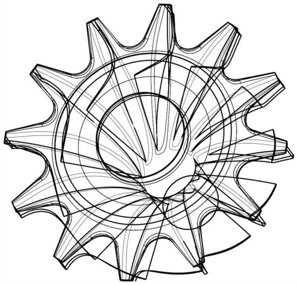
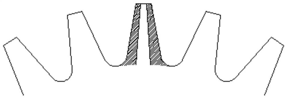
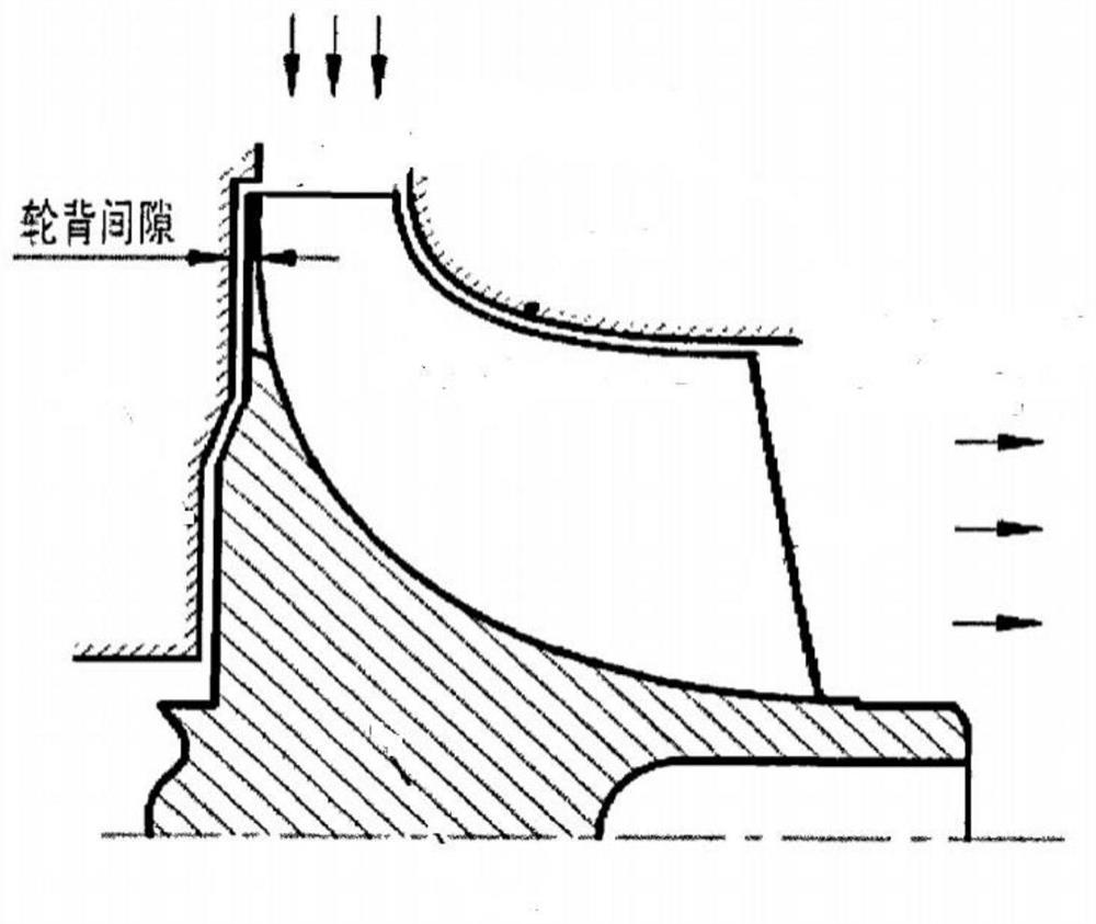
[0037] figure 1 It is a schematic diagram of the three-dimensional structure of the existing semi-open centripetal turbine; figure 2 It is the structural schematic diagram of the existing semi-open centrifugal turbine; image 3 It is one of the structural schematic diagrams of the existing gas turbine engine; Figure 4 It is the second structural schematic diagram of the existing gas turbine engine; Figure 5 is the limiting streamline diagram of the existing semi-open concentric turbine surface; Image 6 is the leakage flow diagram of the wheel back of the existing semi-open centrifugal turbine; Figure 7 It is a partial three-dimensional structural schematic diagram of the semi-open type centripetal turbine according to the preferred embodiment of...


PUM


Abstract

The invention discloses a semi-open centripetal turbine and a gas turbine, which comprise a hub, a disc and blades, the disc is arranged at one end of the hub, the blades are arranged between the hub and the disc, and two adjacent blades form a The turbine airflow passage, the wheel disc includes a wheel back arranged on the hub along the radial direction of the hub, the wheel back is arranged symmetrically along the central axis, a plurality of wheel backs are arranged at intervals along the circumference of the hub, and the wheel backs and blades are arranged in one-to-one correspondence , the wheel back includes a cross-section gradually expanding section, a constant section section and a section tapering section arranged and connected in sequence along the radial direction of the wheel disc. The scraping area dominated by the viscous force at the end blocks the leakage flow dominated by the differential pressure force through the equal section section, thereby reducing the leakage loss of the wheel back. The semi-open centripetal turbine of the present invention has small leakage flow loss and improves the performance and reliability of the semi-open centripetal turbine.

Description

technical field [0001] The present invention relates to the technical field of gas turbine engine combustion chambers, in particular, to a semi-open concentric turbine. Furthermore, the present invention also relates to a gas turbine. Background technique [0002] Gas turbines are generally divided into heavy, medium and small gas turbines according to their power. Small gas turbines have the characteristics of compact structure, high reliability, low maintenance cost and flexible use, and are widely used in vehicle and ship power, distributed energy supply systems and aviation auxiliary power units for various purposes. [0003] Turbine is one of the core components of aero-engine. It converts the thermal energy and potential energy of gas into mechanical energy to drive other devices and equipment. Turbine components must meet the requirements of aerodynamic efficiency, aerodynamic load, and mechanical load. [0004] According to the direction of airflow, turbines can be...

Claims


Application Information

Patent Timeline
Patent Type & Authority Patents(China)
IPC IPC(8): F01D1/22F01D5/04
CPCF01D1/22F01D5/04
Inventor 宋友富曾飞潘尚能
Owner AECC HUNAN AVIATION POWERPLANT RES INST
Learn More