
Embroidery machine power-off protection method and system

A power-off protection, embroidery machine technology, applied in the direction of embroidery machine, embroidery machine mechanism, textile and papermaking, etc., can solve the problems of increasing the workload of operators, machine damage, damage to the machine, etc., to achieve low implementation cost, avoid mistakes Operation, high economic efficiency

Pending Publication Date: 2021-07-02
ZHEJIANG YUELONG SEWING EQUIP
View PDF7 Cites 0 Cited by
  • Summary
  • Abstract
  • Description
  • Claims
  • Application Information

AI Technical Summary

Problems solved by technology

At present, due to the mechanical design of the embroidery machine, if the main shaft of the machine is not at the zero position when it is powered on again, the equipment will not be able to operate and needs to return to the parking space
If the machine is forced to operate, it may damage the machine. At this time, it is necessary to manually turn the main shaft to the zero position to proceed to the next operation, which greatly reduces the work efficiency.
For areas with frequent power failures, such as some backward countries or regions such as Africa, the workload of operators will increase. If operators do not perform manual alignment without knowing it, they may misoperate the machine and cause damage to the machine.

Method used


Image

  • Embroidery machine power-off protection method and system
  • Embroidery machine power-off protection method and system

Examples


Embodiment Construction

[0038]The present invention will be further described in detail below in conjunction with the accompanying drawings and specific embodiments.

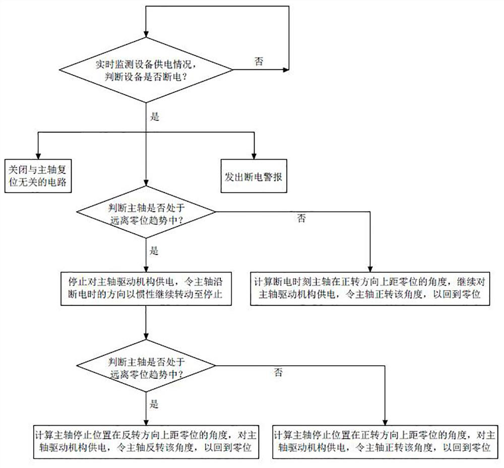
[0039] Such as figure 1 As shown, an embroidery machine power-off protection method includes the following steps:

[0040] Step 1, monitor the power supply of the equipment in real time, and judge whether the equipment is powered off. If so, proceed to steps 2, 3 and 4 at the same time; if not, continue to monitor the power supply of the equipment;

[0041] Step 2, turn off the circuits that are not related to the spindle reset, and store energy for the capacitor in the spindle drive circuit, that is, only open the monitoring circuit of the relevant spindle status or position, so as to avoid the waste of residual electric energy in the circuit and capacitor, so as to ensure that the spindle is reset. required electrical energy;

[0042] Step 3, issue a power failure alarm to notify the staff in time to ensure the timeliness of follow...


PUM


Abstract

The invention discloses an embroidery machine power-off protection method and system, and belongs to the technical field of computerized embroidery machines. The method comprises the following steps that during power failure, if a main shaft is in a rotating trend away from a zero position, power supplying to a main shaft driving mechanism is stopped, and the main shaft is made to continuously rotate with inertia along the direction during power failure until the main shaft is stopped; when the main shaft stops, if the main shaft is in the rotating trend away from the zero position, the main shaft is made to rotate reversely, and power is supplied to the main shaft driving mechanism till the main shaft returns to the zero position; if the main shaft is in the rotating trend close to the zero position, power is supplied to a main shaft driving mechanism, and the main shaft is made to continuously rotate to the zero position along the direction during power failure; and during power failure, if the main shaft is in the rotating trend close to the zero position, power is continuously supplied to the main shaft driving mechanism, so that the main shaft continuously rotates along the direction during power failure until the main shaft returns to the zero position. The main shaft of the embroidery machine can be effectively ensured to return to the parking space during power failure, the restarting efficiency is improved, additional component cost does not need to be increased, and the economic benefit is high.

Description

technical field [0001] The invention relates to the technical field of computerized embroidery machines, in particular to a power-off protection method and system for an embroidery machine. Background technique [0002] At present, the embroidery machines on the market generally do not perform special treatment when the power grid fails, and the machine is in a state of natural power failure and shutdown. At this time, the parking position of the spindle is uncertain. At present, due to the mechanical design of the embroidery machine, if the main shaft of the machine is not at the zero position when it is powered on again, the equipment will not be able to operate and needs to return to the parking space. If the machine is forced to operate, the machine may be damaged. At this time, it is necessary to manually turn the main shaft to the zero position to perform the next operation, which greatly reduces the work efficiency. For areas with frequent power outages, such as some...

Claims


Application Information

Patent Timeline
Patent Type & Authority Applications(China)
IPC IPC(8): D05C13/02
CPCD05C13/02
Inventor 陈天池张汉苗郑邓飞楼凯柴银锋
Owner ZHEJIANG YUELONG SEWING EQUIP
Learn More